Flow control valve

a flow control and valve body technology, applied in valve housings, machines/engines, mechanical equipment, etc., can solve the problems of large heat loss degrade combustion stability, etc., to reduce production costs, maximize fuel economy, and accelerate the warming up of the engine

Active Publication Date: 2020-07-07
HYUNDAI MOTOR CO LTD +1
View PDF7 Cites 6 Cited by
  • Summary
  • Abstract
  • Description
  • Claims
  • Application Information

AI Technical Summary

Benefits of technology

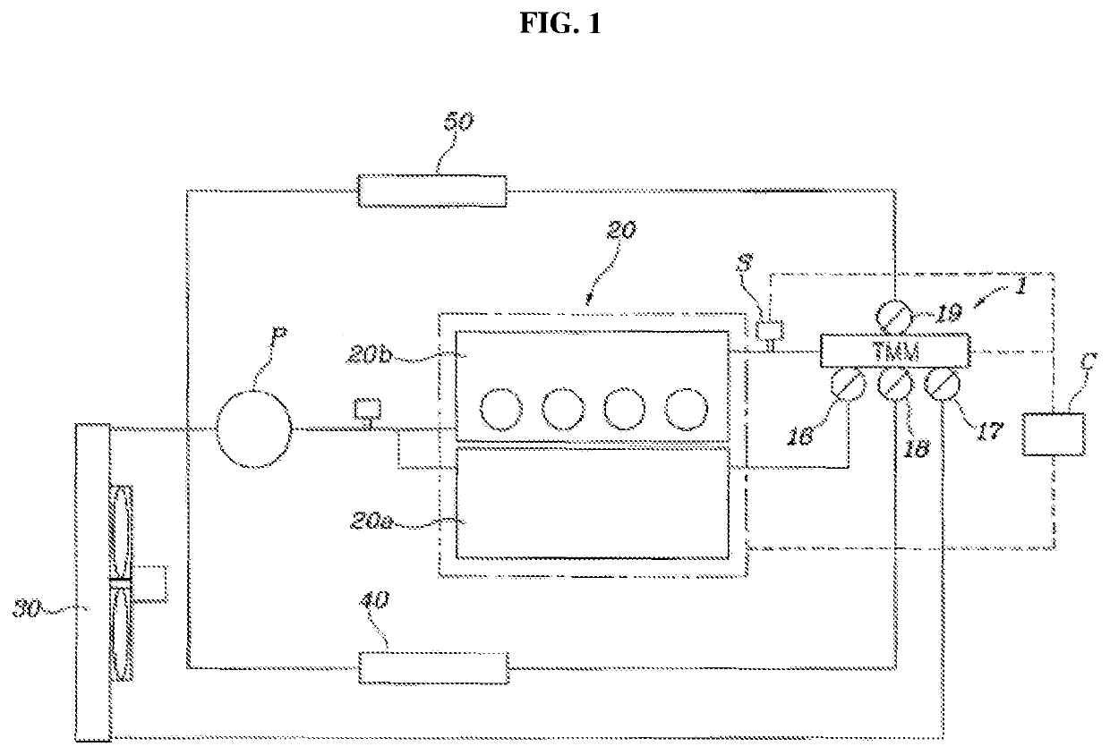
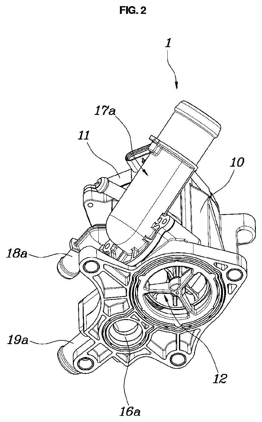
[0029]Through the solutions described above, the present disclosure can perform four-port control for variably controlling four ports at once through the operation of only a flow control valve, and thus can simultaneously implement a variable temperature control technique for increasing the temperature of an entire engine, rapid warming-up of an engine, and a split cooling technique, so as to maximize an improvement in fuel economy. Further, the present disclosure does not require a separate port control structure for implementing a split cooling technique, thereby reducing production costs.
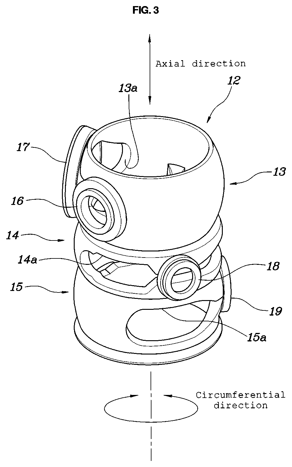
[0030]Also, the present disclosure configures various control sections of a flow control valve depending on driving conditions of the vehicle, the flow control valve being controlled by sequentially passing the control sections, and thus can reduce an operation distance and a number of operations of the flow control valve.
[0031]Further, the present disclosure configures a first heating section, so that there is no coolant flow loss due to unnecessary flow to an oil heat exchanger or an EGR cooler while a flow rate to the heater core side is maximized. Therefore, it is possible to maximize the improvement in fuel economy and the heating performance. In addition, the present disclosure can maximize vehicle cooling performance in high-load conditions, such as when climbing a steep hill.

Problems solved by technology

In particular, in a cold state, the friction of an engine is large due to high viscosity of oil when the oil has a low temperature, a low temperature of a cylinder wall surface causes large heat loss thereto, and combustion stability degrades.
Meanwhile, the temperature of a metal surface of a combustion chamber is increased so that abnormal combustion, such as knocking and pre-ignition, may occur to thus degrade combustion stability.

Method used


Image

  • Flow control valve
  • Flow control valve
  • Flow control valve

Examples


Embodiment Construction

[0042]It is understood that the term “vehicle” or “vehicular” or other similar term as used herein is inclusive of motor vehicles in general such as passenger automobiles including sports utility vehicles (SUV), buses, trucks, various commercial vehicles, watercraft including a variety of boats and ships, aircraft, and the like, and includes hybrid vehicles, electric vehicles, plug-in hybrid electric vehicles, hydrogen-powered vehicles and other alternative fuel vehicles (e.g. fuels derived from resources other than petroleum). As referred to herein, a hybrid vehicle is a vehicle that has two or more sources of power, for example both gasoline-powered and electric-powered vehicles.

[0043]The terminology used herein is for the purpose of describing particular embodiments only and is not intended to be limiting of the disclosure. As used herein, the singular forms “a,”“an” and “the” are intended to include the plural forms as well, unless the context clearly indicates otherwise. It wil...


PUM


Abstract

A flow control valve is arranged to simultaneously perform coolant flow control and variable split cooling, according to control of a path opening degree of the flow control valve. The flow control valve can perform four-port control for variably controlling four ports at once by operation of the flow control valve, and thus can implement variable temperature control for increasing a temperature of an engine, rapid warming-up of the engine, while performing split cooling at the same time.

Description

CROSS REFERENCE TO RELATED APPLICATION[0001]The present application claims under 35 U.S.C. § 119(a) the benefit of Korean Patent Application No. 10-2017-0104000 filed on Aug. 17, 2017, the entire contents of which are incorporated by reference herein.BACKGROUND(a) Technical Field[0002]The present disclosure relates to a flow control valve, more particularly to an integrated flow control valve for vehicle coolant, in which the flow control valve can simultaneously perform flow control of each part of a heat exchanger and cooling components, and a variable split cooling technique for variably and separately cooling each of a cylinder head and a cylinder block, according to control of a path opening degree of the flow control valve.(b) Description of the Related Art[0003]Fuel economy of an engine is reduced in a cold state, such as when a vehicle is initially started, compared to a sufficiently warmed-up condition. In particular, in a cold state, the friction of an engine is large due ...

Claims


Application Information

Patent Timeline
Patent Type & Authority Patents(United States)
IPC IPC(8): F01P7/14F01M5/00F01P7/16F16K11/08F16K11/085F01P3/02F02M26/30
CPCF16K11/08F01M5/002F01P7/165F16K11/0856F01P7/14F01P3/02F01P2025/32F01P2060/18F02M26/30F01P2060/08F01P2003/027F01P2007/146F16K5/08F16K27/06F02M26/22F01M2005/004
Inventor PARK, CHEOL SOOPARK, JUN SIKHAN, BONG HOONCHAE, DONG SUK
Owner HYUNDAI MOTOR CO LTD
Why Eureka
Try Eureka