Magnetic material and method of manufacturing the same

a technology of magnetic materials and materials, applied in the field of magnetic materials, can solve the problems of affecting the implementation of magnetic devices, affecting the reactivity of hard magnetic materials using noble metals such as pt, pd or au, and the upper limit of heat resistance of other devices mounted with magnetic devices and substrates, so as to reduce the cost of raw materials, high magnetic anisotropy, and high reactivity

Active Publication Date: 2020-07-07
TOHOKU UNIV
View PDF12 Cites 0 Cited by
  • Summary
  • Abstract
  • Description
  • Claims
  • Application Information

AI Technical Summary

Benefits of technology

[0018]A first advantageous effect of the present invention is facilitation of manufacturing a hard magnetic material having high magnetic anisotropy. Known hard magnetic materials require a high-temperature process for synthesis. The high-temperature process exerts an adverse influence. Furthermore, it is difficult to process those known hard magnetic materials by a reactive ion etching method. In contrast, a magnetic material according to the present invention can be formed at a room temperature. Thus, a magnetic material according to the present invention requires no high-temperature process. Furthermore, a magnetic material according to the present invention can maintain characteristics after heat treatment at a high temperature. Moreover, a magnetic material according to the present invention includes a transition metal such as Co or Ni, which has relatively high reactivity, as a principal component. Therefore, it is easy to process a magnetic material according to the present invention by a reactive ion etching method.
[0019]A second advantageous effect of the present invention is reduction in raw material cost for manufacturing a hard magnetic material having high magnetic anisotropy, continuous supply of raw materials, and the like. A magnetic material according to the present invention includes a transition metal such as Co or Ni as a principal component. Such a transition metal is available at a lower cost as compared to noble metals such as Pt, Pd, and Au and rare-earth metals such as Sm, Nd, Dy, Tb, and Gd. Furthermore, such a transition metal has overwhelmingly large reserves in the earth. Accordingly, such a transition metal can continuously be supplied over the future.

Problems solved by technology

In this case, other devices mounted with the magnetic device and the substrate have an upper limit of heat resistance.
Thus, a high process temperature hinders implementation of magnetic devices.
Furthermore, a hard magnetic material using a noble metal such as Pt, Pd, or Au generally has low chemical reactivity.
Such reattachment may cause defects in electric characteristics, also cause attachment to an inner wall of the process apparatus so that conditions of the apparatus are deteriorated, and cause generation of particles.

Method used


Image

  • Magnetic material and method of manufacturing the same
  • Magnetic material and method of manufacturing the same
  • Magnetic material and method of manufacturing the same

Examples


example

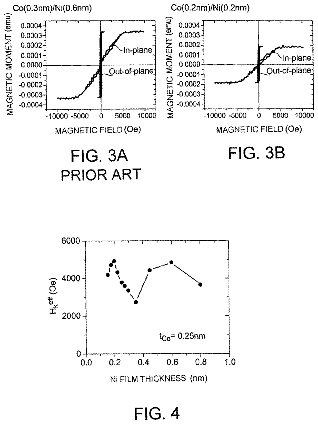
[0040]Next, an example of the present invention will be described with reference to measurement results. FIG. 3A shows magnetization curves of a layered film (magnetic material) in which Co and Ni were stacked while a ratio of the film thickness of Co and Ni was 1:2 as disclosed in Non-Patent Literature 1. FIG. 3B shows magnetization curves of a layered film (magnetic material) according to an example of the present invention in which Co and Ni were alternately stacked such that each layer was formed by substantially one atomic layer. FIGS. 3A and 3B show magnetization curves in a direction perpendicular to the substrate (out-of-plane) and in a direction on a plane of the substrate (in-plane) within the magnetic material. Specific film configurations were Si substrate / Ta (3 nm) / Pt (2.4 nm) / [Co (0.3 nm) / Ni (0.6 nm)]4 / Co (0.3) / Pt (1.5 nm) / Ta (3 nm), and Si substrate / Ta (3 nm) / Pt (2.4 nm) / [Co (0.2 nm) / Ni (0.2 nm)]4 / Co (02) / Pt (1.5 nm) / Ta (3 nm). Those magnetic materials were produced b...


PUM

PropertyMeasurementUnit
thicknessaaaaaaaaaa
thicknessaaaaaaaaaa
thicknessaaaaaaaaaa

Abstract

A magnetic material includes a structure in which a first magnetic layer 1 and a second magnetic layer 2 are stacked such that each layer is formed at least partially in a stacking direction by substantially one atomic layer. The first magnetic layer contains Co as a principal component. The second magnetic layer includes at least Ni. The magnetic material has magnetic anisotropy in the stacking direction. Preferably, an atomic arrangement within a film surface of the first magnetic layer and the second magnetic layer has six-fold symmetry.

Description

TECHNICAL FIELD[0001]The present invention relates to a magnetic material and a method of manufacturing the same.BACKGROUND ART[0002]Magnetic materials are roughly classified into hard magnetic materials and soft magnetic materials. Hard magnetic materials are used for permanent magnets, digital devices, and the like.[0003]Physical characteristics of hard magnetic materials include high magnetically anisotropic energy. Typical examples of hard magnetic materials include Nd—Fe—B, Nd—Dy—Fe—B, Sm—Co, Fe—Pt, Fe—Pd, Co—Pt, Tb—Fe—Co, Gd—Fe—Co, Co—Cr—Pt (each of which is an alloy material), Co / Pt, Co / Pd, Fe / Au (each of which is a nano-laminate material), and the like.[0004]Typical examples of applications of permanent magnets include motors. There are various types of motors. For example, a permanent magnet formed of a hard magnetic material is used for a rotor that rotates within a space in which the polarity of a magnetic field varies with time.[0005]A typical example of digital devices ...

Claims


Application Information

Patent Timeline
Patent Type & Authority Patents(United States)
IPC IPC(8): H01F1/04B32B15/01H01F1/047H01F41/14H01F10/26H01F7/02H01F10/14H01F10/16
CPCH01F1/047H01F1/04H01F10/265H01F41/14H01F7/02B32B15/01H01F10/14H01F10/16Y10T428/12944
Inventor FUKAMI, SHUNSUKESATO, HIDEOYAMANOUCHI, MICHIHIKOIKEDA, SHOJIOHNO, HIDEO
Owner TOHOKU UNIV
Why Eureka
Try Eureka