Depression of copper and iron sulfides in molybdenite flotation circuits

a flotation circuit and copper sulfide technology, applied in the direction of flotation, process efficiency improvement, solid separation, etc., can solve the problems of low mo recovery, many flotation stages, and significant health and safety issues of the process, so as to reduce the slurry ph, improve the overall hse quality, and increase the effect of effectiveness

Active Publication Date: 2020-07-21
TESSENDERLO KERLEY INC
View PDF11 Cites 0 Cited by
  • Summary
  • Abstract
  • Description
  • Claims
  • Application Information

AI Technical Summary

Benefits of technology

[0023]In any of the embodiments of the invention disclosed herein, significant cost and health / safety advantages can be realized by manufacturing the polysulfide depressing reagents on-site or nearby to the separation / flotation plant. Alkaline polysulfide may be manufactured by, for example, reacting sodium hydroxide or calcium hydroxide with sulfur at high temperature. Calcium polysulfide may be prepared by boiling calcium hydroxide and sulfur together with a small amount of surfactant, or as otherwise found in the art. This ability to manufacture depressing agents on-site from substantially non-toxic ingredients is a strong advantage, since most prior art depressing agents are both extremely toxic and are typically manufactured from extremely toxic precursors.
[0038]FIG. 1 shows H2S concentration in headspace above a solution containing calcium polysulfide, a solution containing sodium polysulfide, a solution containing potassium polysulfide, and a solution containing NaHS versus pH. This FIGURE merely shows one of the several advantages of the invention, which is lower hydrogen sulfide evolution at the critical pH values.

Problems solved by technology

Sodium hydrosulfide (NaHS) flotation is the benchmark standard, in very common use, but with inherent HSE (Health, Safety and Environmental) concerns, and also readily releasing toxic H2S when pH is reduced.
This process also has significant health and safety issues, and is generally less effective in comparison to using NaHS.
With some known reagents it may result in low Mo recovery or requires many stages of flotation.

Method used


Image

  • Depression of copper and iron sulfides in molybdenite flotation circuits

Examples


Embodiment Construction

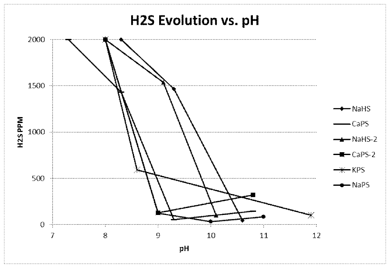
[0040]These chemicals have been laboratory tested successfully using concentrates from three different Cu / Mo operations in the Southwest U.S. and Mexico. A list of typical test parameters is shown below;[0041]Conditioning Time: 1 to 30 Minutes as necessary[0042]Float time: 12 to 30 minutes as necessary.[0043]Froth removal rate: Slow to moderate for good selectivity.[0044]ORP value in Conditioning and Flotation[0045]CaPS: −430 to −580 mV; at 3.4 to 8# / T dosage rate[0046]NaPS: −450 to −560 mV; at 9 to 15# / T dosage rate[0047]KPS: −450 to −560 mV; at 6 to 11# / T dosage rate

NOTE: # / T=pounds reagent per ton of Cu / Mo concentrate feed, dry basis.

[0048]A typical testing protocol that simulates plant operations was used for the testing with some variations depending on the specific plant location and desired parameter optimization. A typical Mo flotation process which is the basis of the simulated testing has Cu / Mo Concentrate flow passing sequentially through a Thickener (˜60% Solids) to a st...


PUM

PropertyMeasurementUnit
Oxidation-Reduction Potentialaaaaaaaaaa
oxidation reduction potentialaaaaaaaaaa

Abstract

A method of depressing copper sulfides and iron sulfides in a molybdenite flotation recovery process that uses alkaline or alkaline earth polysulfides. The method of enriching molybdenite content from a slurry having molybdenite and at least one of iron sulfides and copper sulfides can include the steps of adding an effective amount of a depressing reagent selected from one or more alkaline polysulfides, alkaline earth polysulfides, or a mixture thereof, to the slurry, wherein the pH of the slurry is greater than about 8.0; and passing a gas through the slurry to separate material by selective flotation, and recovering the molybdenite from a froth.

Description

CROSS-REFERENCE TO RELATED APPLICATIONS[0001]This application claims priority to U.S. Provisional Application No. 61 / 978,720 filed on Apr. 11, 2014, and Patent Cooperation Treaty Application No. PCT / US2015 / 025067 filed on Apr. 9, 2015, each titled DEPRESSION OF COPPER AND IRON SULFIDES IN MOLYBDENITE FLOTATION CIRCUITS, the entire contents of both applications being incorporated herein for all legal purposes.TECHNICAL FIELD[0002]The invention relates to a method of recovery of molybdenite from copper / molybdenum sulfide concentrates, iron / molybdenum sulfide concentrates, mixed iron / copper / molybdenum sulfide concentrates, and primary molybdenum sulfide concentrates, as the term concentrates is used in the art, by subjecting a concentrate to a flotation process which uses various chemicals to effect the depression of copper, iron or other sulfide minerals, the improvement being the use of polysulfide treatment additives at elevated pH to depress copper sulfides and iron sulfides.BACKGR...

Claims


Application Information

Patent Timeline
Patent Type & Authority Patents(United States)
IPC IPC(8): B03D1/002B03D1/02B03D1/06
CPCB03D1/028B03D1/02B03D1/06B03D1/002B03D2203/02B03D2201/06Y02P10/20
Inventor DIMITRIADIS, ALEXANDROSCOOK, THEODORE E.
Owner TESSENDERLO KERLEY INC
Why Eureka
Try Eureka