Ultrasound signal processor, ultrasound signal processing method, and ultrasound diagnostic device
a signal processor and ultrasound technology, applied in the field of ultrasonic signal processors, ultrasound signal processing methods, ultrasound diagnostic devices, etc., can solve the problems of difficult application of techniques, inability to keep reduced frame rate, so as to increase the ensemble number, and improve the quality of color doppler images.
- Summary
- Abstract
- Description
- Claims
- Application Information
AI Technical Summary
Benefits of technology
Problems solved by technology
Method used
Image

Examples
first embodiment
[0040]
[0041]Hereinafter, an ultrasound diagnostic device 100 of a first embodiment will be described with reference to the drawings.
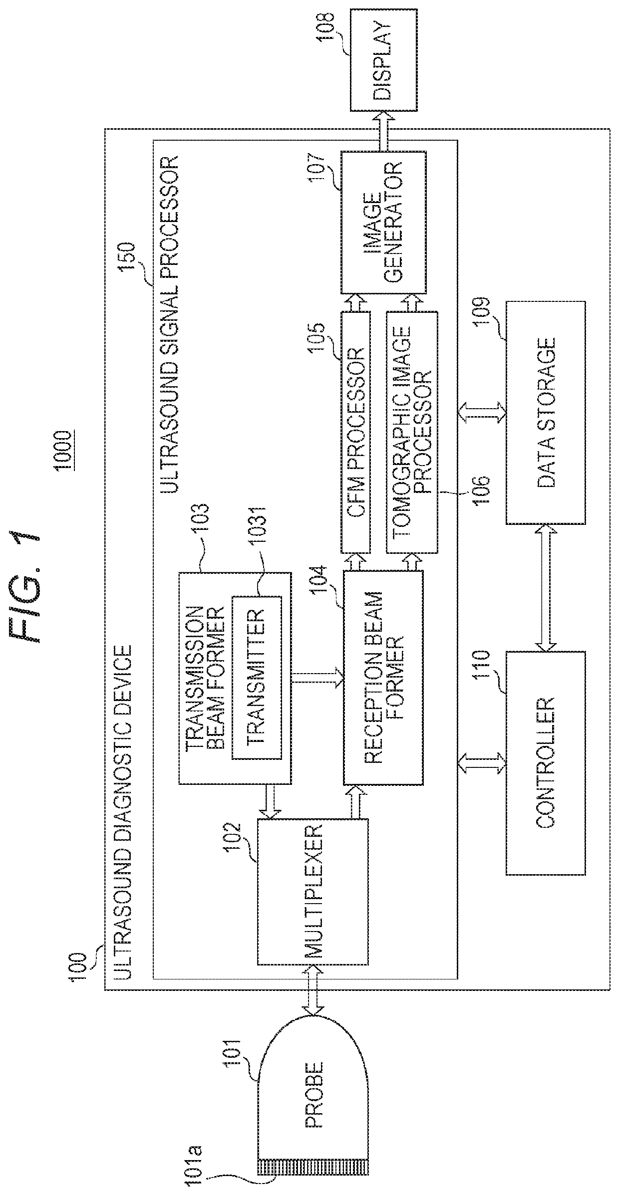
[0042]FIG. 1 is a functional block diagram of an ultrasound diagnostic system 1000 of the first embodiment. As illustrated in FIG. 1, the ultrasound diagnostic system 1000 includes a probe 101 having multiple transducer elements 101a for transmitting ultrasound to a subject and receiving its reflected wave, an ultrasound diagnostic device 100 for causing the probe 101 to perform transmission and reception of ultrasound and generating a ultrasound image on the basis of an output signal from the probe 101, and a display 108 for displaying the ultrasound image on the screen. The probe 101 and the display 108 are each configured to be capable of connecting to the ultrasound diagnostic device 100. FIG. 1 illustrates a state in which the probe 101 and the display 108 are connected to the ultrasound diagnostic device 100. Incidentally, the probe 101 and the di...
first modification
[0161]In the ultrasound diagnostic device 100 of the first embodiment, the phasing adder 1041 is configured to switch two types of methods for calculating the transmission time depending on whether the depth of the observation point P is equal to or greater than, or less than the depth of the transmission focal point F. However, the method for calculating the transmission time is not limited to the two types described in the first embodiment, and also, the reference of the switching is not limited to whether the depth of the observation point P is equal to or greater than, or less than the depth of the transmission focal point F and can be changed if appropriate.
[0162]
[0163]Hereinafter, a method will be described for calculating the transmission time that can be used other than the method described in the first embodiment.
[0164]FIGS. 12A and 12B are schematic views each describing a method for calculating the transmission time that can be used in a case in which the depth of the obs...
second embodiment
[0181]In the first embodiment, for the multiple complex acoustic lines acquired from the same observation point, the velocity estimator 1053 does not distinguish the transmission event set from which the complex acoustic lines are acquired, and uses the complex acoustic lines all as ensembles. In a second embodiment, configurations of the transmission beam former and the reception beam former are similar to those in the first embodiment; however, processing of velocity estimation differs from that in the first embodiment. In the first embodiment, for the same observation point, there is no distinction among the complex acoustic line signal acquired inside the target area Bx1, the complex acoustic line signal acquired inside the sub-target area Bx2, and the complex acoustic line signal acquired inside the sub-target area Bx3. Among the main target area Bx1, the sub-target area Bx2, and the sub-target area Bx3, the reception beam forming method, specifically, the method for calculatin...
PUM
 Abstract
Description
Claims
Application Information