Terminal heat exchanger for an electrical connector

a heat exchanger and terminal technology, applied in the direction of contact heating/cooling, coupling device connection, climate sustainability, etc., can solve the problem of damage to the components of the charging inlet assembly

Active Publication Date: 2020-08-25
TYCO ELECTRONICS LOGISTICS AG (CH) +1
View PDF6 Cites 17 Cited by
  • Summary
  • Abstract
  • Description
  • Claims
  • Application Information

AI Technical Summary

Problems solved by technology

However, at higher currents, the terminals and the power cables experience an increase in temperature, which may damage the components of the charging inlet assembly.

Method used


Image

  • Terminal heat exchanger for an electrical connector
  • Terminal heat exchanger for an electrical connector
  • Terminal heat exchanger for an electrical connector

Examples


Embodiment Construction

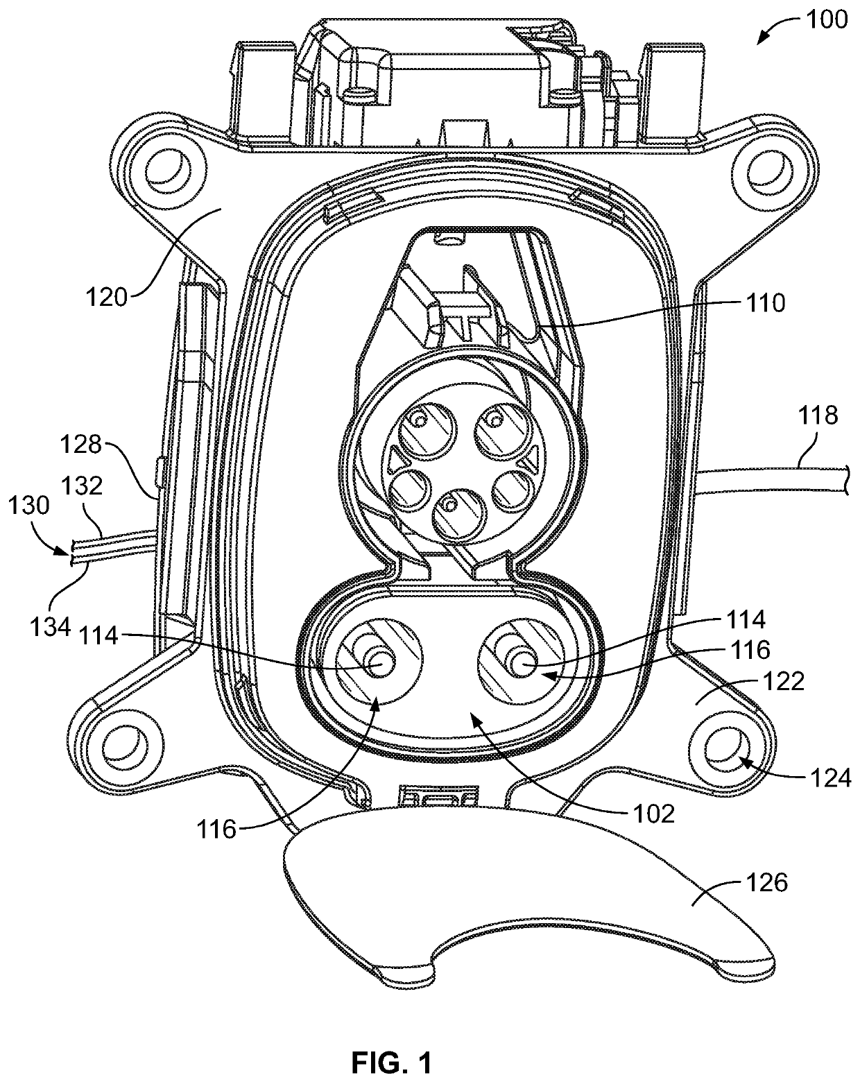
[0029]FIG. 1 is a front perspective view of an electrical connector 102 having a cooling system 130 for cooling components of the electrical connector 102 in accordance with an exemplary embodiment. The electrical connector 102 may be a power connector, such as a power connector of a charging inlet assembly 100. While the electrical connector 102 may be described herein as part of the charging inlet assembly, it is realized that the electrical connector 102 may be another type of electrical connector.

[0030]The charging inlet assembly 100 is used as a charging inlet for a vehicle, such as an electric vehicle (EV) or hybrid electric vehicle (HEV). The charging inlet assembly 100 includes an electrical connector 102 configured for mating reception with a charging connector (not shown). In an exemplary embodiment, the electrical connector 102 is configured for mating with a DC fast charging connector, such as the SAE combo CCS charging connector, in addition to AC charging connectors, s...


PUM


Abstract

An electrical connector includes a housing that extends between a front and a rear. The housing has a chamber at the rear. The housing has a terminal channel between the front and the rear. A terminal is coupled to the housing. The terminal includes a mating pin at a front of the terminal and a cable connector at a rear of the terminal. The mating pin is positioned in the terminal channel for mating with a charging connector. The cable connector is positioned in the chamber at the rear of the housing. A terminal heat exchanger is positioned in the chamber. The terminal heat exchanger is thermally coupled to the cable connector of the terminal. The terminal heat exchanger has a separator electrically isolating the terminal heat exchanger from the terminal.

Description

BACKGROUND OF THE INVENTION[0001]The subject matter herein relates generally to heat exchangers for electrical connectors.[0002]Electrical connectors, such as power connectors, generate heat when current flows through the terminals and cables of the power connectors. For example, an electrical connector of a charging inlet assembly for a battery system of an electric vehicle (EV) or hybrid electric vehicle (HEV) may generate heat through the terminals and the cables of the charging inlet assembly during a charging process. A charging connector is configured to be mated with the terminals of the charging inlet assembly to charge the battery system of the vehicle. It is desirable to increase the current transmitted through the terminals for charging the battery. However, at higher currents, the terminals and the power cables experience an increase in temperature, which may damage the components of the charging inlet assembly.[0003]A need remains for an electrical connector having a co...

Claims


Application Information

Patent Timeline
Patent Type & Authority Patents(United States)
IPC IPC(8): H01R13/50H01R24/66H01R4/02H02J7/00B60L53/16H01R13/00H01R13/422H01H1/62H01R103/00
CPCH01R4/029B60L53/16H02J7/0045H01R24/66H01R13/50H01R2103/00H01R2201/26H01R13/005H01H1/62H01R13/4223H01R13/502H01R13/405H05K7/2039H05K7/20272H01M10/625Y02E60/10H01M2220/20H01M10/44H01M50/50Y02T10/70Y02T10/7072Y02T90/14B60L53/302Y02T90/12
Inventor SARRAF, DAVID BRUCESCHMIDT, HELGEMYER, NATHAN PHILIPDE CHAZAL, AARON JAMES
Owner TYCO ELECTRONICS LOGISTICS AG (CH)
Why Eureka
Try Eureka