Input/output module

a technology of input/output module and output/output module, which is applied in the direction of logic circuit coupling/interface arrangement, program control, instruments, etc., can solve the problems of monitoring unit, power supply voltage cannot be monitored, physical size of i/o module increases, etc., to prevent delay in timing at which the programmable logic controller outputs the operation stop command to the control-target apparatus, and prevent the safety of workers working in the periphery.

Active Publication Date: 2020-08-25
DENSO WAVE INC
View PDF6 Cites 0 Cited by
  • Summary
  • Abstract
  • Description
  • Claims
  • Application Information

AI Technical Summary

Benefits of technology

[0025]According to the exemplary embodiment, both the power supply voltage and the monitoring unit can be subjected to an abnormality diagnosis by a simple configuration in which a single comparator is provided for a monitoring target. As a result, compared to a configuration in which two comparators are provided for a monitoring target, increase in the number of constituent components can be suppressed.
[0048]According to the exemplary embodiment, a delay in the timing at which communication is interrupted can be prevented even in cases in which, after the actual power supply voltage falls below the lower-limit value of the operable voltage range during the period in which the input voltage of the threshold terminal is the high-voltage-side threshold, the power supply voltage that is inputted to the monitoring target temporarily exceeds the high-voltage-side threshold as a result of superimposed noise.

Problems solved by technology

Here, in cases in which an abnormality occurs in the monitoring unit, the power supply voltage cannot be monitored.
In this regard, when the I / O module includes, in addition to the monitoring unit, the second monitoring unit that monitors whether or not an abnormality has occurred in the monitoring unit, a problem occurs in that the physical size of the I / O module increases.
For example, the abnormality in the monitoring unit includes an abnormality in which the drive state of the switch cannot be switched (stuck at on or off).
When foreign matter, such as dust, infiltrates the I / O module and attaches to the switch or the drive unit that outputs the drive signal of the switch, erroneous operation of the switch may occur.
In addition, when noise is superimposed on the drive signal which turns the switch on and off, erroneous operation of the switch may occur.
When erroneous operation of the switch occurs, for example, regardless of abnormalities in the power supply voltage and the monitoring unit not actually having occurred, the logic of the output signal of the comparator remains unchanged over the determination time and the abnormality in the power supply voltage or the monitoring unit may not be accurately diagnosed.
Therefore, foreign matter does not easily infiltrate into the I / O module.
The control unit may interrupt communication between the programmable logic controller and the safety apparatus when the diagnosing unit makes the diagnosis that an abnormality has occurred.
Here, when an abnormality in which the power supply voltage falls outside of the operable voltage range occurs, the safety apparatus may be unable to transmit the emergency stop signal to the control-target apparatus via the control unit.
Therefore, the timing at which the amount of time clocked by the clock unit reaches the determination time becomes delayed.
As a result, the amount of time until the diagnosis that an abnormality has occurred is made after the actual power supply voltage exceeds the upper-limit value becomes long.
As a result, the output timing of the operation stop command from the programmable logic controller to the control-target apparatus is delayed.
This delay is undesirable in terms of ensuring the safety of the workers who are working in the periphery of the control-target apparatus.

Method used


Image

  • Input/output module
  • Input/output module
  • Input/output module

Examples


first embodiment

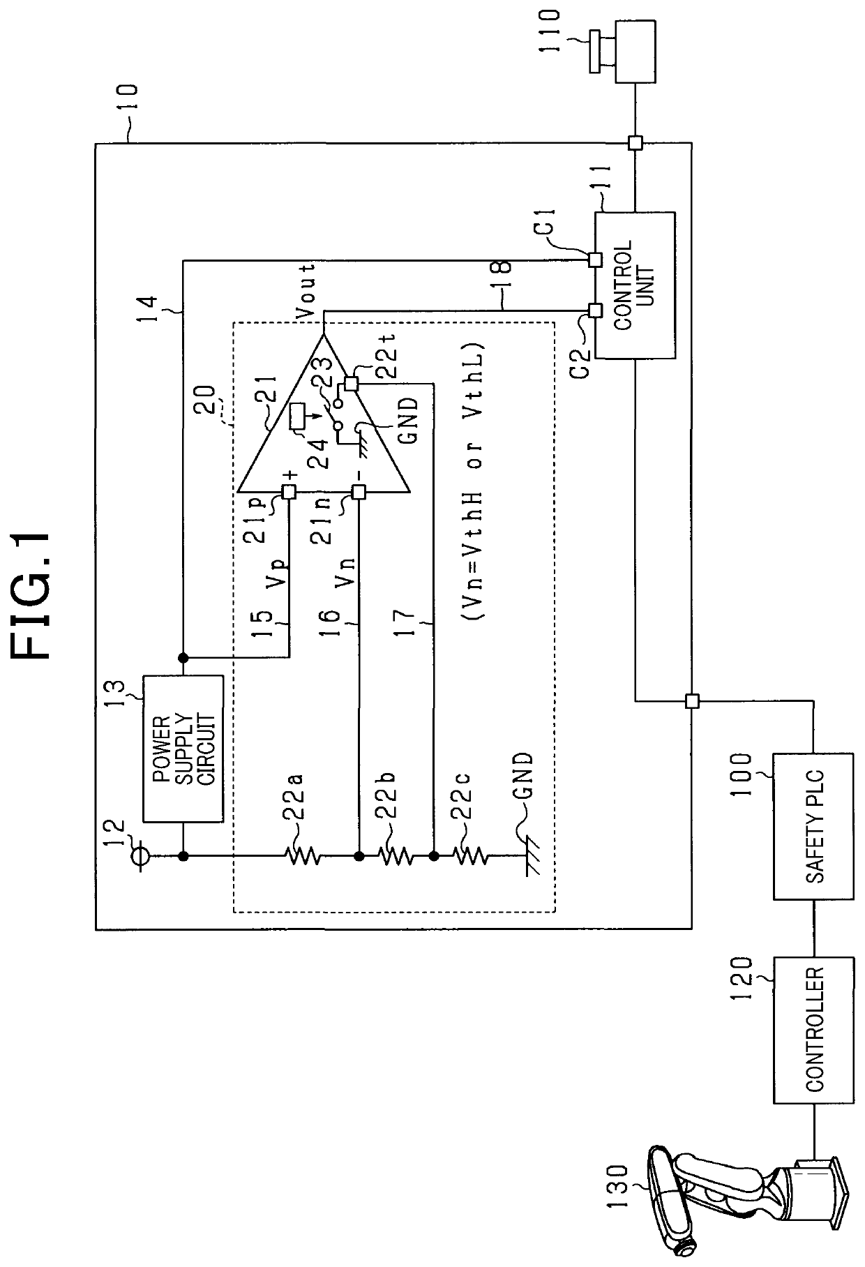
[0061]A first embodiment actualizing an I / O module of the present disclosure will hereinafter be described with reference to the drawings. The I / O module according to the present embodiment configures an industrial robot system that is used in an assembly system in a machine assembly plant or the like.

[0062]As shown in FIG. 1, the robot system includes an I / O module 10, a safety PLC 100, an emergency stop switch 110, a controller 120, and a robot 130. The emergency stop switch 110 serves as a safety apparatus. According to the present embodiment, the safety PLC 100 corresponds to a first external apparatus. The emergency stop switch 110 corresponds to a second external apparatus.

[0063]The safety PLC 100 is connected to the controller 120 by a cable. The controller 120 is connected to the robot 130 by a cable. The safety PLC 100 outputs operation commands for the robot 130 to the controller 120. The controller 120 controls the operation of the robot 130 based on the operation command...

second embodiment

[0102]A second embodiment will be described below with reference to the drawings, mainly focusing on the differences with the first embodiment. As shown in FIG. 6, according to the present embodiment, a switch 25 that is turned on and off to change the input voltage Vn of the inverting input terminal 21n is provided inside the control unit 11, rather than the comparator 21. In FIG. 6, configurations that are identical to the configurations shown in FIG. 1, described above, are given the same reference numbers for convenience.

[0103]A third terminal C3 of the control unit 11 is connected to the connection point between the second resistor 22b and the third resistor 22c by the third wiring 17. The ground GND is connected to the third terminal C3 with the switch 25 therebetween. The control unit 11 turns on and off the switch 25 every predetermined amount of time TL.

[0104]According to the above-described embodiment, effects based on the effects according to the first embodiment can be a...

third embodiment

[0105]A third embodiment will be described below with reference to the drawings, focusing on the differences with the first embodiment. FIG. 7 shows the control unit 11 according to the present embodiment. The control unit 11 includes a clock unit 11a, a diagnosing unit 11b, an inversion determining unit 11c, and a filtering unit 11d.

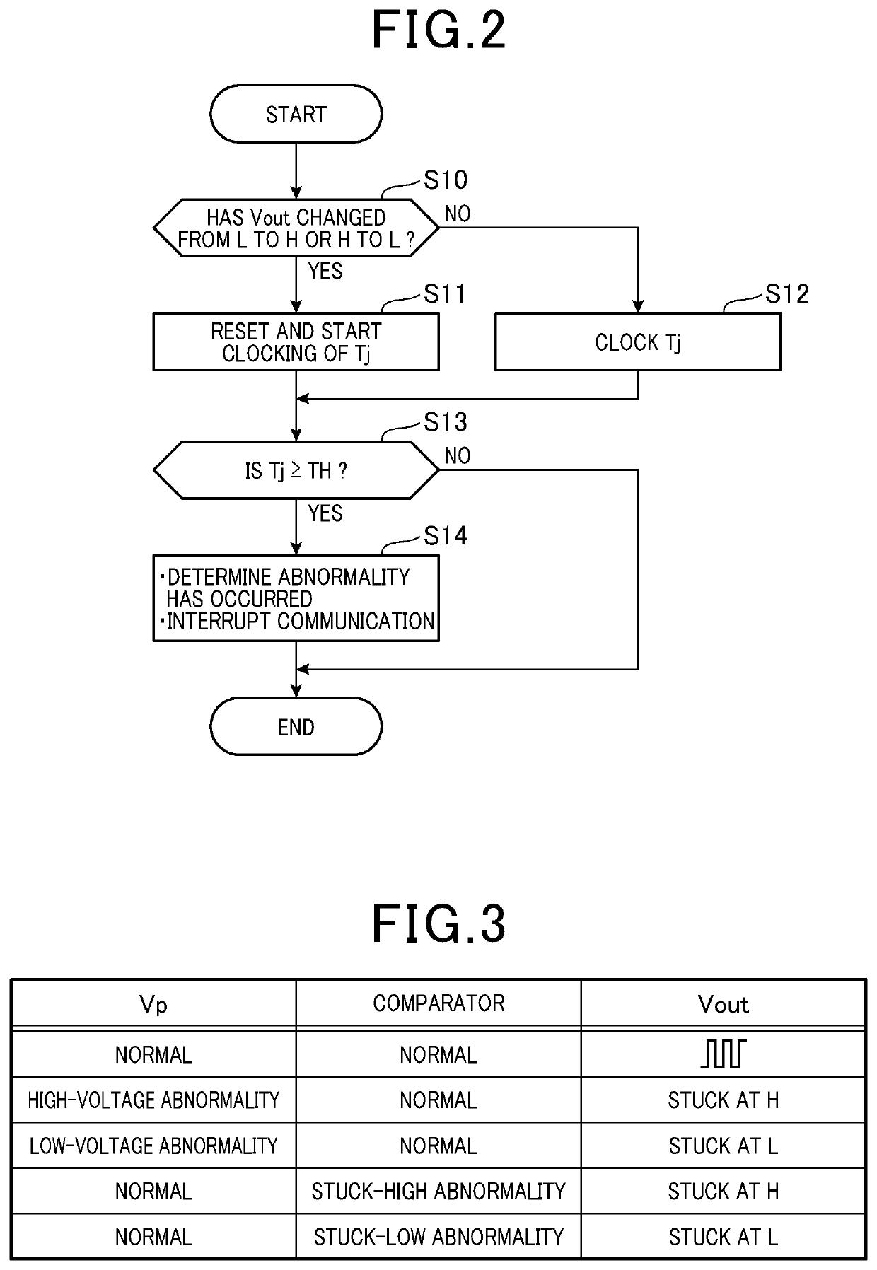
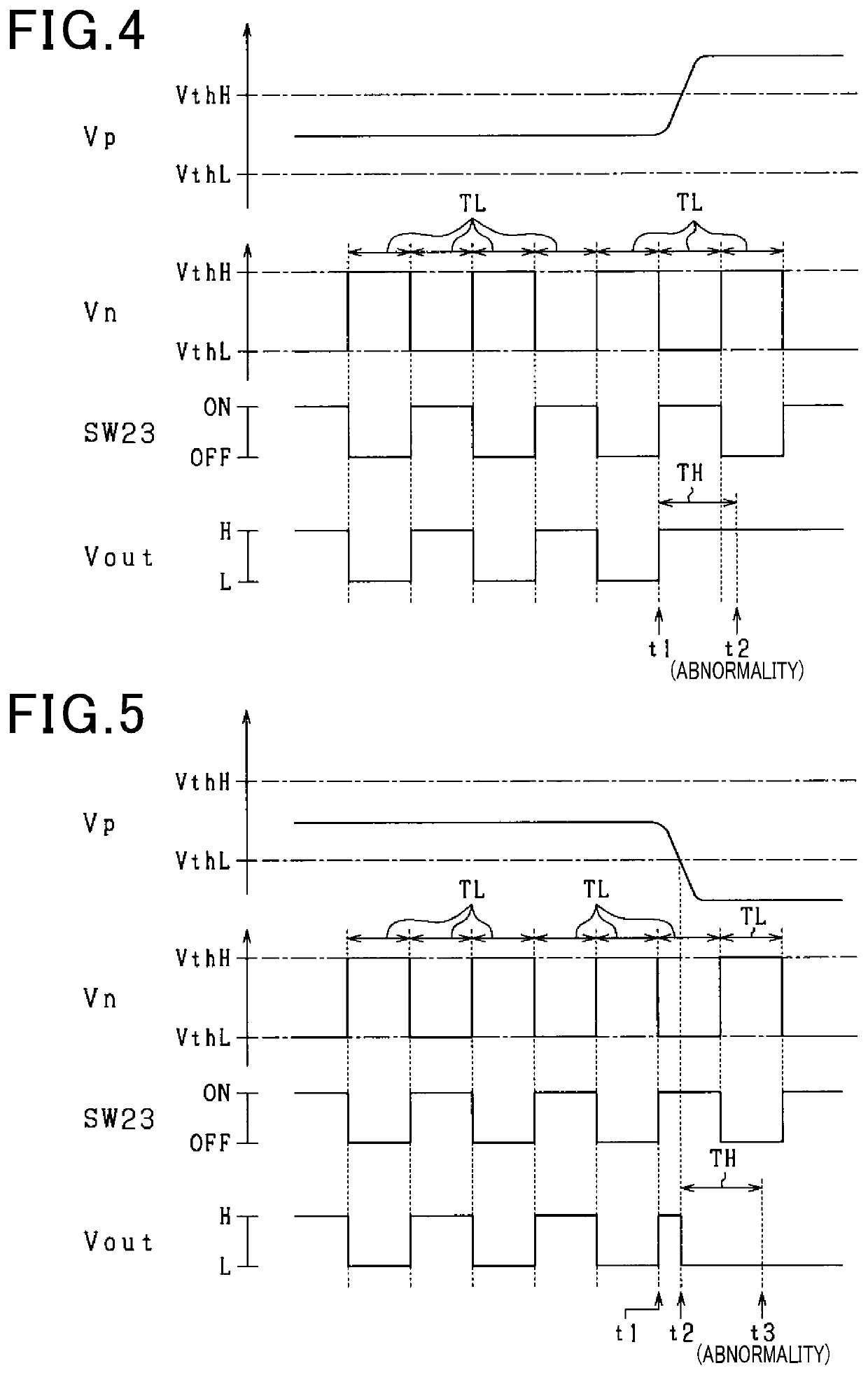
[0106]As described above regarding steps S10 and S11 in FIG. 2, the clock unit 11a acquires a logic inversion timing of the diagnosis signal Vout as the reference timing and clocks the amount of time over which the logic level of the diagnosis signal Vout does not change as the elapsed time Tj, using the acquired reference timing as the computation-start timing.

[0107]As described above regarding steps S13 and S14 in FIG. 2, the diagnosing unit 11b makes a diagnosis that an abnormality in which the power supply voltage Vp falls outside of the operable voltage range or an abnormality in the monitoring unit 20 has occurred when the clocked elapsed time Tj...


PUM


Abstract

An input / output module includes a control unit and a monitoring unit. The monitoring unit includes a series-connection body including three or more resistors, a comparator, a connection path, and a switch. One of inverting and non-inverting input terminals of the comparator serves as a monitoring terminal, and the other serves as a threshold terminal. Input voltage of the threshold terminal when the switch is turned off is set to a high-voltage-side threshold, and the input voltage when the switch is turned on is set to a low-voltage-side threshold. The control unit makes a diagnosis that an abnormality in which the power supply voltage falls outside of an operable voltage range or an abnormality in the monitoring unit has occurred, when logic of an output signal of the comparator is determined to be unchanged over a determination time that is a longer amount of time than a predetermined amount of time.

Description

CROSS-REFERENCE TO RELATED APPLICATION[0001]This application is based on and claims the benefit of priority from earlier Japanese Patent Application No. 2017-119841, filed Jun. 19, 2017, the description of which is incorporated herein by reference.BACKGROUNDTechnical Field[0002]The present disclosure relates to an input / output (I / O) module.Related Art[0003]An I / O module that performs communication among a plurality of external apparatuses is conventionally known. Hereafter, an example of the I / O module will be described. This example performs communication between a safety programmable logic controller (PLC) and an emergency stop switch. The safety PLC outputs operation commands to an industrial robot.[0004]The I / O module includes a control unit that acquires an output signal of the emergency stop switch. The control unit then outputs a signal corresponding to the acquired signal to the safety PLC. When the signal corresponding to the output signal of the emergency safety switch is ...

Claims


Application Information

Patent Timeline
Patent Type & Authority Patents(United States)
IPC IPC(8): H02H7/20H03K19/0175H02H3/20G05B19/048G05B19/05H02H1/00G05B23/02H03K5/24
CPCH02H3/207H02H7/20G05B19/048G05B19/054H03K19/017581H02H1/0007G05B2219/1181H03K5/24G05B23/0275Y04S10/52
Inventor MAEKAWA, TAKAAKI
Owner DENSO WAVE INC
Why Eureka
Try Eureka