Method for producing and purifying RNA, comprising at least one step of tangential flow filtration

a technology of tangential flow filtration and purification method, which is applied in the direction of instruments, membrane technology, chemistry apparatus and processes, etc., can solve the problems of not being able to provide rna of high purity, not being able to achieve efficient purification, and not being able to provide precipitation. achieve the effect of double the concentration of solute molecules

Active Publication Date: 2020-09-01
CUREVAC REAL ESTATE GMBH
View PDF76 Cites 14 Cited by
  • Summary
  • Abstract
  • Description
  • Claims
  • Application Information

AI Technical Summary

Benefits of technology

[0039]HPLC: High-performance liquid chromatography (HPLC; formerly referred to as high-pressure liquid chromatography), is a technique in analytic chemistry used to separate the components in a mixture, to identify each component, and to quantify each component. It relies on pumps to pass a pressurized liquid solvent containing the sample mixture through a column filled with a solid adsorbent material. Each component in the sample interacts slightly differently with the adsorbent material, causing different flow rates for the different components and leading to the separation of the components as they flow out the column. HPLC is distinguished from traditional (“low pressure”) liquid chromatography because operational pressures are significantly higher (50-350 bar), while ordinary liquid chromatography typically relies on the force of gravity to pass the mobile phase through the column. Due to the small sample amount separated in analytical HPLC, typical column dimensions are 2.1-4.6 mm diameter, and 30-250 mm length. Also HPLC columns are made with smaller sorbent particles (2-50 micrometer in average particle size). This gives HPLC superior resolving power when separating mixtures, which is why it is a popular chromatographic technique. The schematic of an HPLC instrument typically includes a sampler, pumps, and a detector. The sampler brings the sample mixture into the mobile phase stream which carries it into the column. The pumps deliver the desired flow and composition of the mobile phase through the column. The detector generates a signal proportional to the amount of sample component emerging from the column, hence allowing for quantitative analysis of the sample components. A digital microprocessor and user software control the HPLC instrument and provide data analysis. Some models of mechanical pumps in a HPLC instrument can mix multiple solvents together in ratios changing in time, generating a composition gradient in the mobile phase. Various detectors are in common use, such as UV / Vis, photodiode array (PDA) or based on mass spectrometry. Most HPLC instruments also have a column oven that allows for adjusting the temperature the separation is performed at.
[0241]In a preferred embodiment, the optional termination of transcription of step C1) may comprise the addition of an effective amount of a cation complexing agent such as EDTA. EDTA may efficiently stop the in vitro transcription reaction and also deactivates nucleases and stabilizes the RNA due to the depletion of divalent cations. Moreover, addition of EDTA to the IVT-mix results in partial reduction of potentially occurring turbidity. It was also found that the addition of EDTA allows higher flow rates during subsequent TFF steps.

Problems solved by technology

RNA is emerging as an innovative candidate for a variety of pharmaceutical applications, but efficient purification is continuing to be a challenge.
This is partly due to the different types and combinations of undesired contaminants in a sample that need to be separated from a desired RNA species to obtain a pure RNA sample.
However, precipitation is not the method of choice in large-scale production processes since precipitation and resolubilization of nucleic acids is time consuming.
However, the authors report that this method does not provide RNA of high purity, as it does not completely remove contaminants such as DNA and protein.
Furthermore, the method involves the use of organic solvents and is laborious and time-consuming, involving as many as 36 steps requiring extensive manual sample handling at different conditions, including at least one overnight incubation step.
Therefore, while this procedure may satisfy requirements for research and laboratory-scale RNA purification, it suffers from a low degree of RNA purity, reproducibility and is unsuitable for purification of pharmaceutical-grade RNA on a commercial scale for implementation in an industrial process.
However, the described nucleic acid loading amounts of the membrane are very low and would therefore require huge membrane areas for the large-scale production (g to kg) of mRNA.
Non-limiting examples of undesired constituents of RNA- or DNA-containing samples which therefore need to be depleted may comprise degraded fragments or fragments which have arisen as a result of premature termination of transcription, or also excessively long transcripts if plasmids are not completely linearized.
Furthermore, intermediates may be depleted from the sample such as e.g. template DNA.
It usually does not have an open reading frame and thus does not provide a peptide-antigen or immunogen but elicits an innate immune response e.g. by binding to a specific kind of Toll-like-receptor (TLR) or other suitable receptors.

Method used


Image

  • Method for producing and purifying RNA, comprising at least one step of tangential flow filtration
  • Method for producing and purifying RNA, comprising at least one step of tangential flow filtration
  • Method for producing and purifying RNA, comprising at least one step of tangential flow filtration

Examples


example 1

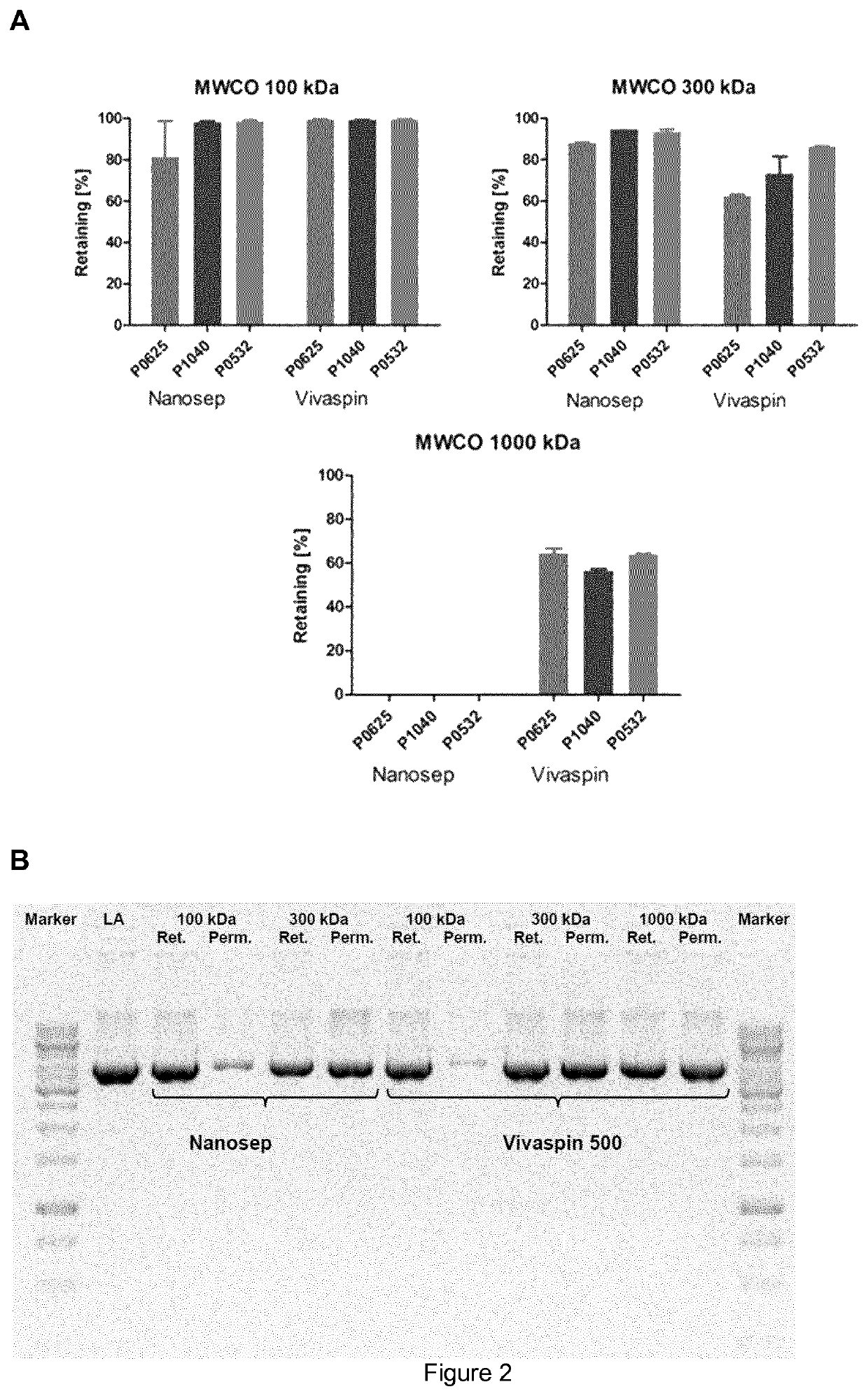
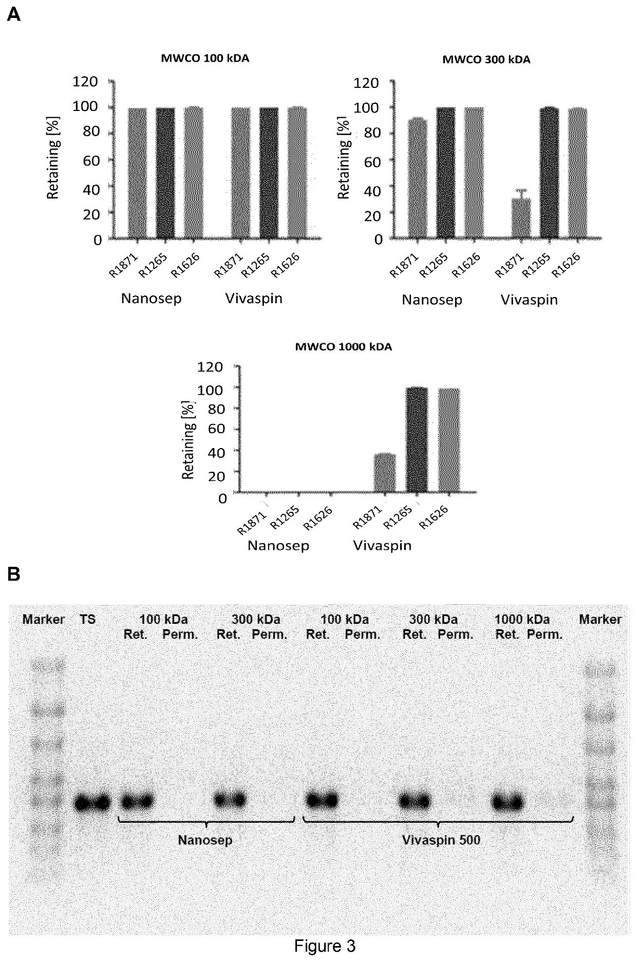
[0315]The following materials of Table 1 were used in the subsequent experimental section:

[0316]

TABLE 1MaterialsEquipmentManufacturerVivaflow 50, PES, 100 kDaSartoriusSartocon Slice 200 100 kDa, PESSartoriusSartocon Slice 200 100 kDa, HydrosartSartorius(cellulose-based membrane)Sartcocon Slice 200 300 kDa, PESSartoriusOmega Centramate T OS100T02, PES 100 kDaPALL GmbHNovaSet-LS ProStream (Low BindingNovaSepmPES), 100 kDaHollow fibre module, 100 kDa, PESGE-HealthcareSpin-Filter Nanosep ® (100 kDa), PESPall GmbHSpin-Filter Nanosep ® (300 kDa), PESPall GmbHSpin-Filter Nanosep ® (1000 kDa), PESPall GmbHSpin-Filter Vivaspin ® 500 (100 kDa), PESSartoriusSpin-Filter Vivaspin ® 500 (300 kDa), PESSartoriusSpin-Filter Vivaspin ® 500 (1000 kDa), PESSartoriusVivaflow 50 Modul, PES, 100 kDaSartoriusSartoflow Slice 200, PES, 100 kDaSartorius

General Methods

example 2

tion of Plasmid DNA

[0317]The following conditions were used for linearization of the plasmid DNA:

1 μg plasmid DNA

0.5 μl reaction buffer

3 Units restriction enzyme EcoRI

Add. 5 μl with WFI (water for injection)

[0318]The reaction was incubated for 3 hours at 37° C. and stopped by heat-inactivation of the restriction enzyme (65° C., 30 minutes).

example 3

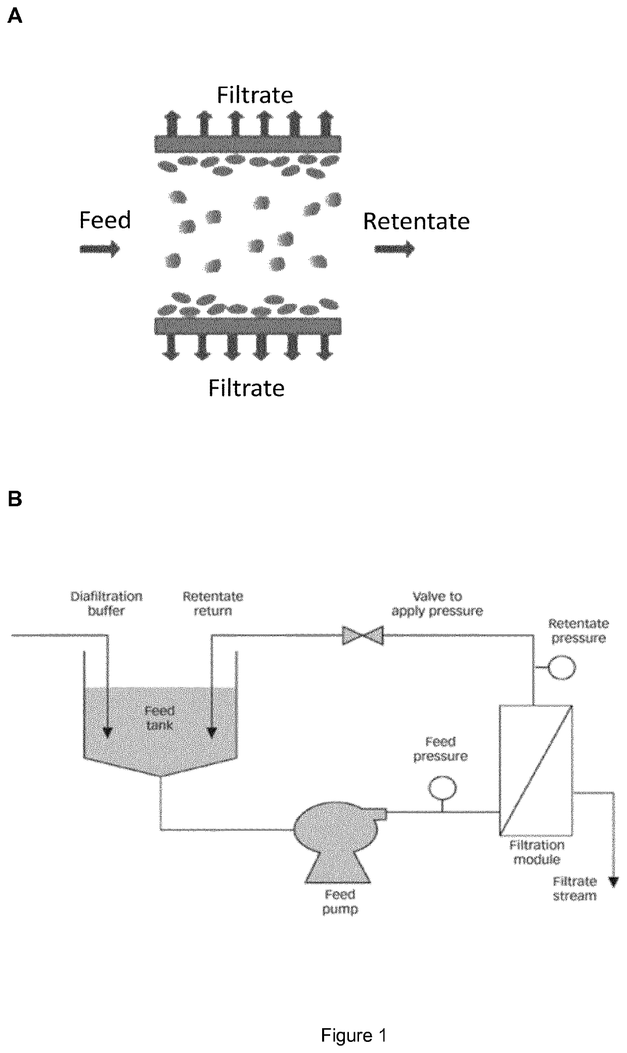
escription of the TFF Process

[0319]All tubes and the retentate vessel were cleaned with 75% EtOH and water and were assembled. The membrane cassette was fixed into the corresponding holder, according to the manufacturer's instruction, and respectively the hollow fibre membrane was connected to the system.

[0320]Afterwards, the system and membrane was flushed with at least 1 L water, 1 L 1 M or 0.5 M NaOH for 1 hour (for removal of potential contaminants, like RNases) and was washed again with water, until pH value in the permeate was neutral. Subsequently, the whole system was flushed with water for injection (WFI) or diafiltration solution or buffer.

3.1—Concentration Step

[0321]DNA / RNA-solution was filled into the retentate vessel, and was optionally concentrated to the required concentration, by setting the indicated pressures.

3.2—Diafiltration Step

[0322]After the optional concentration step, diafiltration was started. Therefore the diafiltration tube was placed into the diafiltrati...


PUM


Abstract

The present invention relates to method for producing and purifying RNA comprising the steps of providing DNA encoding the RNA; transcription of the DNA into RNA; and conditioning and / or purifying of the solution comprising transcribed RNA by one or more steps of tangential flow filtration (TFF).

Description

[0001]The present invention was made with support from the Government under Agreement No. HR0011-11-3-0001 awarded by DARPA. The Government has certain rights in the invention.[0002]This application is a national phase application under 35 U.S.C. § 371 of International Application No. PCT / EP2016 / 062152, filed May 30, 2016, which claims benefit of International Application No. PCT / EP2015 / 062002, filed May 29, 2015, the entire contents of each of which are hereby incorporated by reference.TECHNICAL FIELD[0003]The present invention relates to methods of tangential flow filtration (TFF) for producing and purifying RNA.BACKGROUND OF THE INVENTION[0004]RNA is emerging as an innovative candidate for a variety of pharmaceutical applications, but efficient purification is continuing to be a challenge. This is partly due to the different types and combinations of undesired contaminants in a sample that need to be separated from a desired RNA species to obtain a pure RNA sample. Such contamina...

Claims


Application Information

Patent Timeline
Patent Type & Authority Patents(United States)
IPC IPC(8): C12N15/10C12P19/34G01N30/02B01D71/12B01D61/14
CPCB01D61/145C12N15/1017B01D71/12C12P19/34G01N30/02G01N2030/027C12N15/101
Inventor FUNKNER, ANDREASDORNER, STEFANIESEWING, STEFANIEKAMM, JOHANNESBROGHAMMER, NORBERTKETTERER, THOMASMUTZKE, THORSTEN
Owner CUREVAC REAL ESTATE GMBH
Why Eureka
Try Eureka