Magnetic recording write head with write pole having a tapered trailing end section with negative magnetic anisotropy

a write pole and negative magnetic anisotropy technology, applied in the field of perpendicular magnetic recording system, can solve the problems of reducing the writability of the write pole to the recording layer, shunting a portion of the flux from the write pole, and the likelihood of unwanted flux path, so as to reduce the writability of the write head and reduce the flux to the recording layer. , the effect of reducing the writability of the write pol

Active Publication Date: 2020-09-01
WESTERN DIGITAL TECH INC
View PDF16 Cites 3 Cited by
  • Summary
  • Abstract
  • Description
  • Claims
  • Application Information

AI Technical Summary

Benefits of technology

[0004]In PMR write heads a narrow write gap and narrow side gaps can increase the likelihood of an unwanted flux path from the write pole, which reduces the writability of the write head to the recording layer. Thus a problem associated with PMR write heads is shunting of a portion of the flux from the write pole into the write gap and the side gaps. This reduces the flux to the recording layer, resulting in a reduction in BPI and TPI. This also results in a loss in overwrite (OW) performance. OW is a measure of the residual signal detected from a first written pattern after that pattern has been overwritten by a second pattern and is an important parameter for high performance disk drives.
[0005]In embodiments of this invention the write pole includes a main portion formed of conventional high-moment magnetic materials, and a beveled or tapered trailing portion formed of a Co / Fe multilayer with negative magnetic anisotropy (negative anisotropy constant or —Ku). The Co / Fe multilayer tapered trailing portion has a high saturation magnetization (Ms) and thus functions as part of the write pole to direct the flux perpendicularly to the recording layer. Also, the —Ku Co / Fe multilayer tapered trailing portion has its hard axis oriented substantially orthogonal to the layer thickness and thus substantially prevents flux leakage into the write gap. In other embodiments the —Ku Co / Fe multilayer is also formed on the sides of the write pole in the cross-track direction adjacent the side gaps.

Problems solved by technology

In PMR write heads a narrow write gap and narrow side gaps can increase the likelihood of an unwanted flux path from the write pole, which reduces the writability of the write head to the recording layer.
Thus a problem associated with PMR write heads is shunting of a portion of the flux from the write pole into the write gap and the side gaps.
This also results in a loss in overwrite (OW) performance.

Method used


Image

  • Magnetic recording write head with write pole having a tapered trailing end section with negative magnetic anisotropy
  • Magnetic recording write head with write pole having a tapered trailing end section with negative magnetic anisotropy
  • Magnetic recording write head with write pole having a tapered trailing end section with negative magnetic anisotropy

Examples


Embodiment Construction

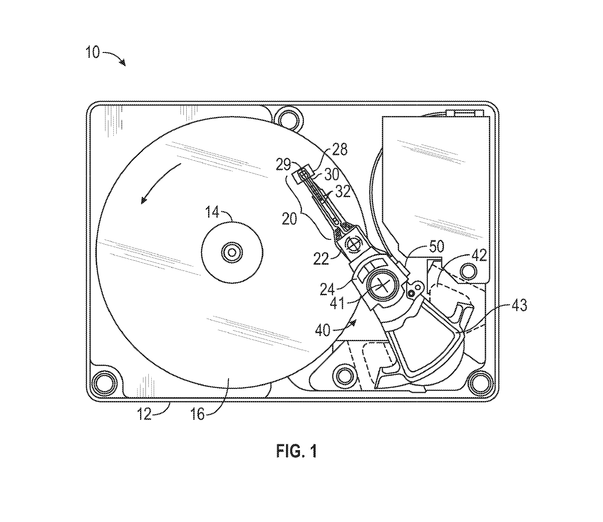
[0013]FIG. 1 is a top plan view of a conventional head / disk assembly of a hard disk drive with the cover removed that may function with the write head embodiments of the invention. The disk drive 10 includes a rigid base 12 supporting a spindle 14 that supports a stack of disks, including top disk 16. The spindle 14 is rotated by a spindle motor (not shown) for rotating the disks in the direction shown by curved arrow on disk 16. The hard disk drive 10 has at least one load beam assembly 20 having an integrated lead suspension (ILS) or flexure 30 with an array 32 of electrically conductive interconnect traces or lines. The load beam assemblies 20 are attached to rigid arms 22 connected to an E-shaped support structure, sometimes called an E-block 24. Each flexure 30 is attached to a gas-bearing slider 28. A magnetic recording read / write head 29 is located at the end or trailing surface of slider 28. The flexure 30 enables the slider 28 to “pitch” and “roll” on a gas-bearing (typical...


PUM

PropertyMeasurementUnit
thicknessaaaaaaaaaa
thicknessesaaaaaaaaaa
thicknessaaaaaaaaaa

Abstract

A perpendicular magnetic recording write head includes a main portion formed of conventional high-moment magnetic materials, and a beveled or tapered trailing portion formed of a Co / Fe multilayer with negative magnetic anisotropy (negative anisotropy constant or —Ku). The Co / Fe multilayer tapered trailing portion has a high saturation magnetization (Ms) and thus functions as part of the write pole to direct the flux perpendicularly to the recording layer. Also, the —Ku Co / Fe multilayer tapered trailing portion has its hard axis oriented substantially orthogonal to the layer thickness and thus substantially prevents flux leakage into the write gap. The —Ku Co / Fe multilayer may also be formed on the sides of the write pole in the cross-track direction to prevent flux leakage into the side gaps.

Description

BACKGROUNDField of the Invention[0001]This invention relates generally to perpendicular magnetic recording (PMR) systems, and more particularly to a PMR write head having an improved write pole.Description of the Related Art[0002]Perpendicular magnetic recording (PMR) in magnetic recording hard disk drives, wherein the recorded bits are stored in a perpendicular or out-of-plane orientation in the magnetic recording layer of the disk, allows for ultra-high recording density, i.e., the areal density of the recorded bits on the disk. To achieve high areal bit density the PMR write head must be able to write at high bit density (bits per inch or BPI) in the along-the-track direction but also at narrow track widths to achieve high tracks per inch (TPI) in the cross-track direction.[0003]The PMR write head includes a write pole, a trailing shield, and a write gap with non-magnetic material between the write pole and the trailing shield. The trailing shield improves the magnetic field grad...

Claims


Application Information

Patent Timeline
Patent Type & Authority Patents(United States)
IPC IPC(8): G11B5/31G11B5/11G11B5/127
CPCG11B5/315G11B5/11G11B5/1278G11B5/3153
Inventor SONG, SUPINGLI, ZHANJIEWEI, YAGUANGLAM, TERENCE TIN-LOKHO, KUOK SAN
Owner WESTERN DIGITAL TECH INC
Why Eureka
Try Eureka