Power transmission device and power reception device

a technology of power transmission device and power reception device, which is applied in the direction of transformer/inductance magnetic core, charging station, transportation and packaging, etc., can solve the problem of power transmission device problems, and achieve excellent transmission, increase and improve the coupling coefficient between the power transmission device and the power reception device

Active Publication Date: 2020-09-01
TOYOTA JIDOSHA KK
View PDF83 Cites 2 Cited by
  • Summary
  • Abstract
  • Description
  • Claims
  • Application Information

AI Technical Summary

Benefits of technology

[0013]The magnetic flux flowing so as to extend over the first adjacent portion and the second adjacent portion is more likely to expand upward, with the result that this magnetic flux is more likely to reach the power reception device disposed above the power transmission device.
[0015]The first adjacent portion and the second adjacent portion are located closer to the power reception device than the first spacer portion and the second spacer portion are. Thus, the magnetic flux formed so as to extend over the first adjacent portion and the second adjacent portion (the magnetic firm from the power transmission device) is more likely to reach the power reception device. Accordingly, the coupling coefficient between the power transmission device and the power reception device can be increased.
[0016]The coupling coefficient between the power transmission device and the power reception device can be improved. Thus, even when the first coil and the second coil are reduced in size, electric power can be excellently transmitted to the power reception device, and the power transmission device can be reduced in size.

Problems solved by technology

The same problem occurs also in the power transmission device.

Method used


Image

  • Power transmission device and power reception device
  • Power transmission device and power reception device
  • Power transmission device and power reception device

Examples


first embodiment

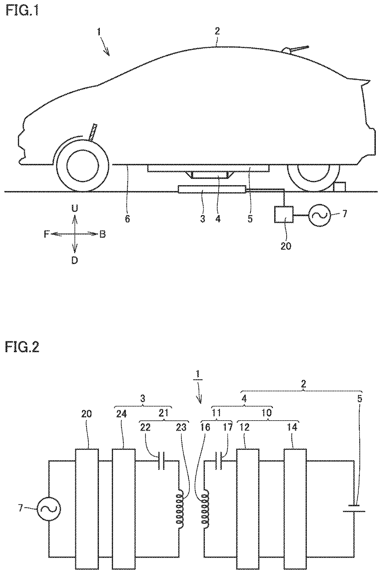
[0048]FIG. 1 is a schematic diagram schematically showing a contactless charging system 1. Contactless charging system 1 includes a power transmission device 3, a vehicle 2, a power supply 7, and a converter 20.

[0049]Power supply 7 is connected to converter 20. Converter 20 includes an inverter and a converter.

[0050]Vehicle 2 includes a power reception device 4 and a power storage device 5. In an example shown in FIG. 1, power storage device 5 is provided on the lower surface of a floor panel 6 of vehicle 2. Power reception device 4 is provided on the lower surface of power storage device 5.

[0051]Power reception device 4 includes a resonator 11 and equipment 10. Resonator 11 includes a power reception coil 16 and a capacitor 17. Capacitor 17 is connected in series to power reception coil 16. Capacitor 17 and power reception coil 16 constitute an LC resonator. Resonator 11 has a Q value of 100 or more. Equipment 10 includes a rectifier 12 and a filter 14. Rectifier 12 is connected to...

second embodiment

[0155]Then, a power transmission device 38 and a power reception device 4B according to the second embodiment will be hereinafter described with reference to FIG. 17 and the like.

[0156]FIG. 17 is a perspective view showing a part of power transmission device 3B according to the present second embodiment. Power transmission device 3B includes a power transmission coil 23 and a ferrite plate 35B.

[0157]Power transmission coil 23 of power transmission device 3B according to the present second embodiment has the same shape as that of power transmission coil 23 in the first embodiment.

[0158]FIG. 18 is a perspective view schematically showing ferrite plate 35B. Ferrite plate 35B includes a divided ferrite plate 46B and a divided ferrite plate 47B. Divided ferrite plate 46B includes a plate portion 200 and a protruding portion 201. Plate portion 200 is formed in a plate shape.

[0159]Protruding portion 201 is formed on the upper surface of plate portion 200. Protruding portion 201 includes a ...

third embodiment

[0201]Referring to FIG. 24 and the like, a power transmission device 3C and a power reception device 4C according to the present third embodiment will be hereinafter described.

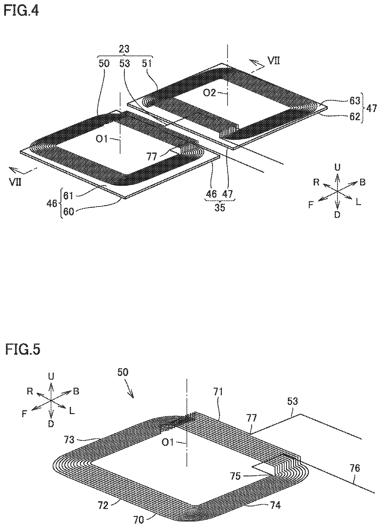
[0202]FIG. 24 is a plan view showing a power transmission coil 23C of power transmission device 3C. FIG. 25 is a perspective view showing power transmission coil 23C of power transmission device 3C. Power transmission coil 23C includes a first coil 50 and a second coil 51. First coil 50 includes an adjacent portion 71, a spacer portion 72, and connection portions 73 and 74.

[0203]Adjacent portion 71 includes a recess portion 78. Recess portion 78 is formed so as to be away from adjacent portion 81 of second coil 51.

[0204]Recess portion 78 is formed in the center portion of adjacent portion 71 in the direction in which adjacent portion 71 extends. In examples shown in FIGS. 24 and 25, adjacent portion 71 is formed so as to be away from second coil 51 from the end of adjacent portion 71 toward the center portion ...


PUM

PropertyMeasurementUnit
frequencyaaaaaaaaaa
frequencyaaaaaaaaaa
frequencyaaaaaaaaaa

Abstract

A power transmission device includes: a first coil; and a second coil. The first coil and the second coil are configured such that a first current direction and a second current direction are opposite to each other. The first coil includes a first adjacent portion located adjacent to the second coil, and a first spacer portion located on an opposite side of the first adjacent portion. The second coil includes a second adjacent portion located adjacent to the first coil, and a second spacer portion located on an opposite side of the second adjacent portion with respect to the second winding axis. The first adjacent portion is located higher than the first spacer portion.

Description

CROSS-REFERENCE TO RELATED APPLICATIONS[0001]This a nonprovisional application claims priority to Japanese Patent Application No. 2017-130400 filed on Jul. 3, 2017 with the Japan Patent Office, the entire contents of which are hereby incorporated by reference.BACKGROUNDField[0002]The present disclosure relates to a power transmission device and a power reception device.Description of the Background Art[0003]Conventionally, a contactless charging system configured to contactlessly transmit electric power has been known. A contactless charging system includes a power transmission device and a power reception device. The power transmission device is configured to contactlessly transmit electric power to the power reception device (see Japanese Patent Laying-Open Nos. 2013-154815, 2013-146154, 2013-146148, 2013-110822, and 2013-126327).[0004]For example, a vehicle charging pad disclosed in Japanese Patent National Publication No. 2016-526280 includes a first coil, a second coil and a mo...

Claims


Application Information

Patent Timeline
Patent Type & Authority Patents(United States)
IPC IPC(8): H01F38/14H01F27/24H02J50/40H01F27/28B60L53/12H02J7/02H02J50/12
CPCB60L53/12H01F38/14H02J50/12H01F27/2871H02J50/40H01F27/24B60L2210/30B60L2210/40B60L2210/10B60L2240/70B60L2240/36H01F27/36H02J50/402B60L53/122H02J50/005Y02T10/7072Y02T10/70Y02T90/14Y02T90/12
Inventor YUASA, HIROAKI
Owner TOYOTA JIDOSHA KK
Why Eureka
Try Eureka