Manufacturing method of micro channel structure

a manufacturing method and micro channel technology, applied in mechanical equipment, machines/engines, positive displacement liquid engines, etc., can solve the problems of achieve the effects of stable structural size and flatness of the micro channel structure of the present disclosure, increased reliability and service life of operation, and low cost of development and mass production

Active Publication Date: 2020-10-13
MICROJET TECH
View PDF9 Cites 0 Cited by
  • Summary
  • Abstract
  • Description
  • Claims
  • Application Information

AI Technical Summary

Benefits of technology

[0005]The object of the present disclosure is to provide a manufacturing method of a micro channel structure. Being manufactured by a standardized micro-electromechanical system (MEMS) process, the micro channel structure can be driven by driving power sources having different phases to achieve fluid transportation. Therefore, the costs of development and mass production are low. Moreover, the structural size and flatness of the micro channel structure of the present disclosure are stable, and it benefits to make the reliability and service life of the operation increase.

Problems solved by technology

Therefore, the costs of development and mass production are low.

Method used


Image

  • Manufacturing method of micro channel structure
  • Manufacturing method of micro channel structure
  • Manufacturing method of micro channel structure

Examples


Embodiment Construction

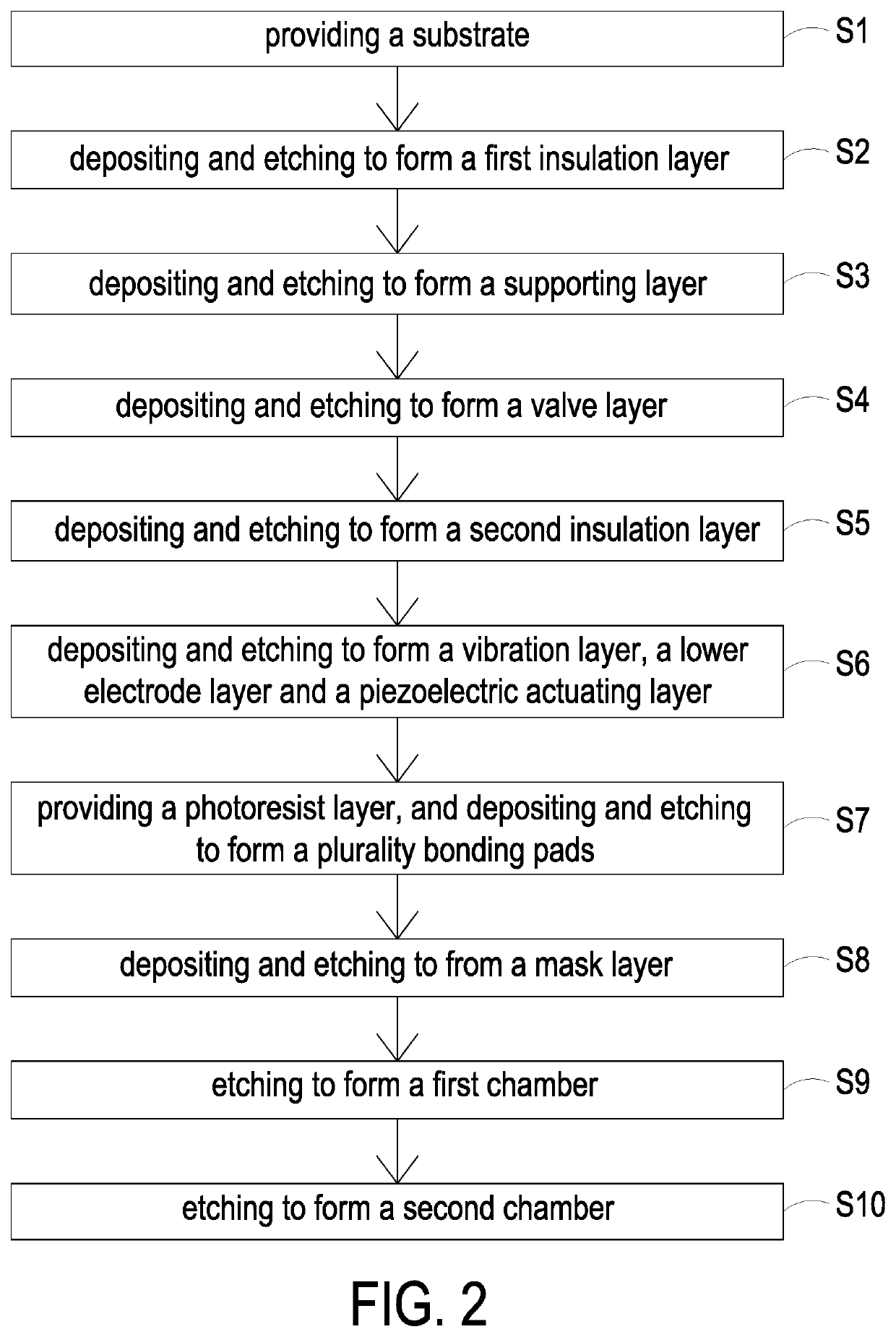
[0016]The present disclosure will now be described more specifically with reference to the following embodiments. It is to be noted that the following descriptions of preferred embodiments of this disclosure are presented herein for purpose of illustration and description only. It is not intended to be exhaustive or to be limited to the precise form disclosed.

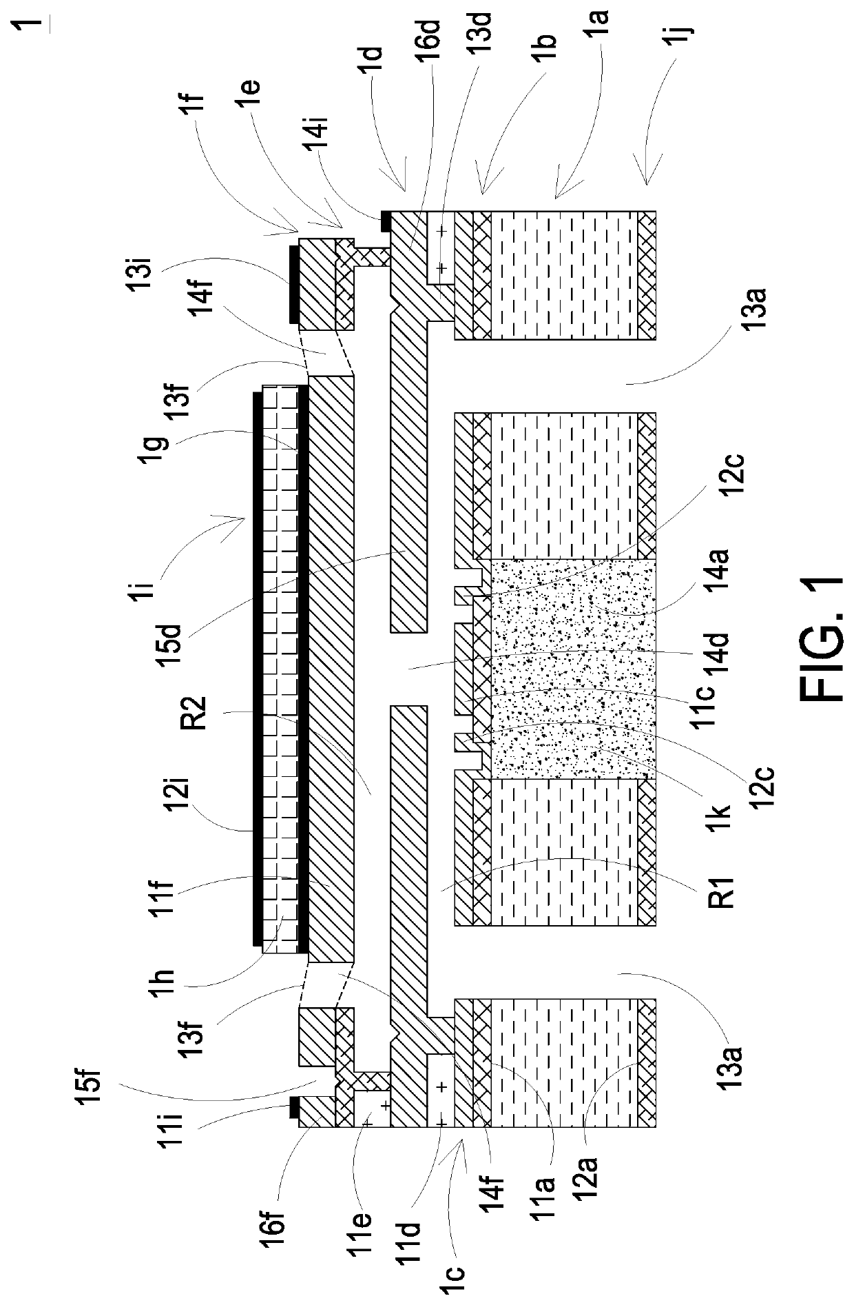
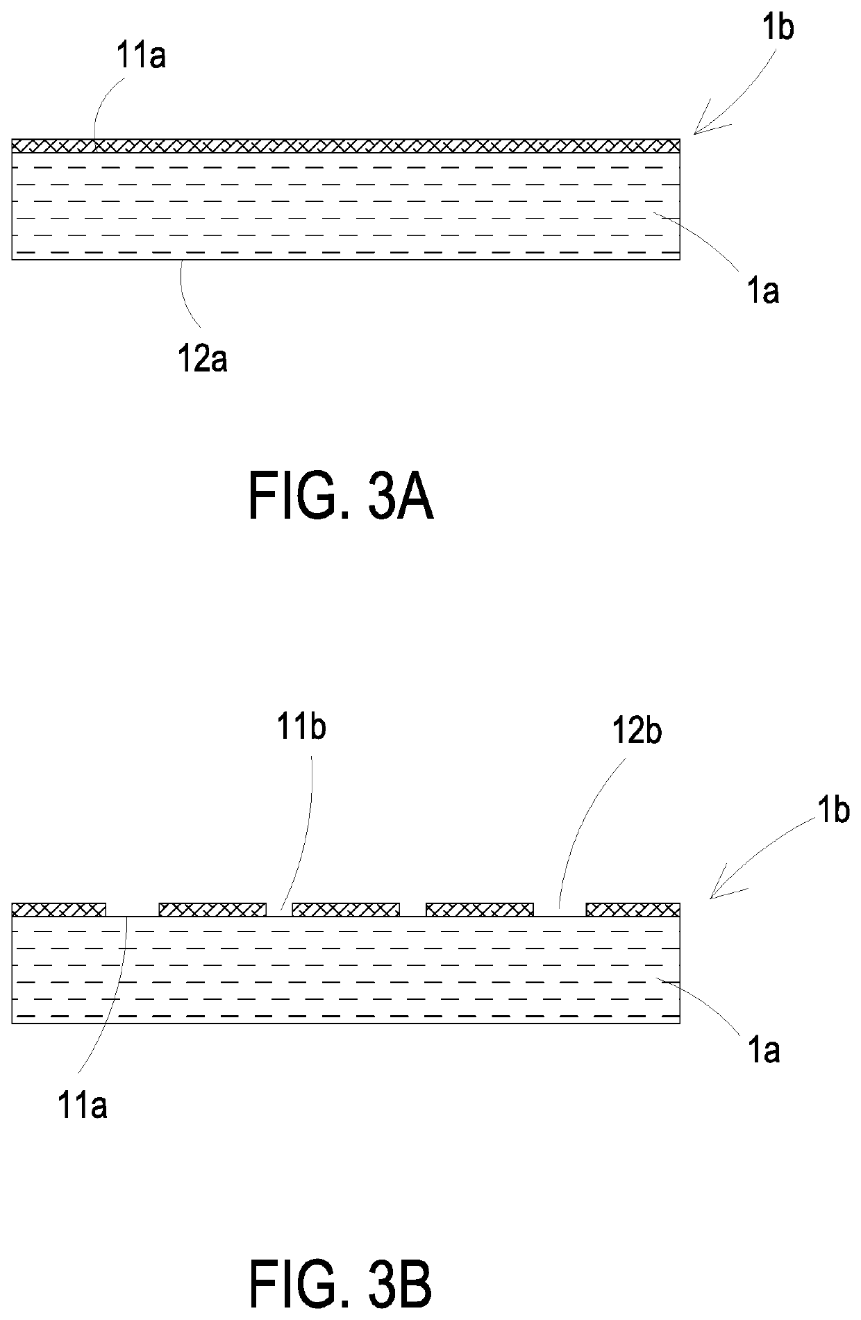
[0017]Please refer to FIG. 1. The present disclosure provides a micro channel structure 1 including at least one substrate 1a, at least one first surface 11a, at least one second surface 12a, at least one first insulation layer 1b, at least one insulation material, at least one supporting layer 1c, at least one conductive material, at least one protruding part 11c, at least one conductive part 12c, at least one valve layer 1d, at least one first oxide layer 11d, at least one first anchor zone 12d, at least one base part 13d with a height, at least one movable part 15d, at least one fixed part 16d, at least one hollow aperture 1...


PUM

PropertyMeasurementUnit
thicknessaaaaaaaaaa
heightaaaaaaaaaa
thicknessaaaaaaaaaa

Abstract

A manufacturing method of micro channel structure is disclosed and includes steps of: providing a substrate; depositing and etching to form a first insulation layer; depositing and etching to form a supporting layer; depositing and etching to form a valve layer; depositing and etching to form a second insulation layer; depositing and etching to form a vibration layer, a lower electrode layer and a piezoelectric actuating layer; providing a photoresist layer and depositing and etching to form a plurality of bonding pads; depositing and etching to from a mask layer; etching to form a first chamber; and etching to form a second chamber.

Description

FIELD OF THE DISCLOSURE[0001]The present disclosure relates to a manufacturing method of a micro channel structure, and more particularly to a manufacturing method of a micro channel structure driven by driving power sources having different phases.BACKGROUND OF THE DISCLOSURE[0002]Currently, in all fields, the products used in many sectors such as pharmaceutical industries, computer techniques, printing industries or energy industries are developed toward elaboration and miniaturization. The fluid transportation devices are important components that are used in for example micro pumps, micro atomizers, printheads or the industrial printers.[0003]With the rapid advancement of science and technology, the application of fluid transportation device tends to be more and more diversified. For the industrial applications, the biomedical applications, the healthcare, the electronic cooling and so on, even the most popular wearable devices, the fluid transportation device is utilized therei...

Claims


Application Information

Patent Timeline
Patent Type & Authority Patents(United States)
IPC IPC(8): F04B19/00B81C1/00F16K99/00H01L29/04B82Y40/00F04B37/00
CPCB81C1/00492B81C1/00119F16K99/0048B81C1/00071B81C1/00166F04B19/006F16K2099/0074F16K2099/0094
Inventor MOU, HAO-JANYU, RONG-HOCHANG, CHENG-MINGTAI, HSIEN-CHUNGLIAO, WEN-HSIUNGHUANG, CHI-FENGHAN, YUNG-LUNGTSAI, CHANG-YEN
Owner MICROJET TECH
Why Eureka
Try Eureka