DC/AC inverter system supplied by integrated power networks to increase output power with robust auto stop control

Active Publication Date: 2020-10-13
FORD GLOBAL TECH LLC
View PDF17 Cites 6 Cited by
  • Summary
  • Abstract
  • Description
  • Claims
  • Application Information

AI Technical Summary

Benefits of technology

[0009]The invention enables an increase in available power for supporting AC loads during vehicle Auto Stop. In this design, a pair of auxiliary batteries for a high voltage power net are connected in parallel, and the parallel combination is connected in series with a low voltage (e.g., 12V) power net. A total number and size of batteries for the combined power nets is the same as for separate power nets of the prior ar

Problems solved by technology

Providing a duplicate battery and alternator just for the AC power outlet(s), however, can result in significant manufacturing costs.
In addition, packaging space for the components in the vehicle is limited.
A potential disadvantage of the use of small capacity batteries, however, is that it limits the amount of time that the AC power outlet can be used without the internal combustion engine running (i.e., the time that the AC inverter operates on battery power without any contribution by the alternator).
The smaller batteries are also less effective

Method used


Image

  • DC/AC inverter system supplied by integrated power networks to increase output power with robust auto stop control
  • DC/AC inverter system supplied by integrated power networks to increase output power with robust auto stop control
  • DC/AC inverter system supplied by integrated power networks to increase output power with robust auto stop control

Examples


first embodiment

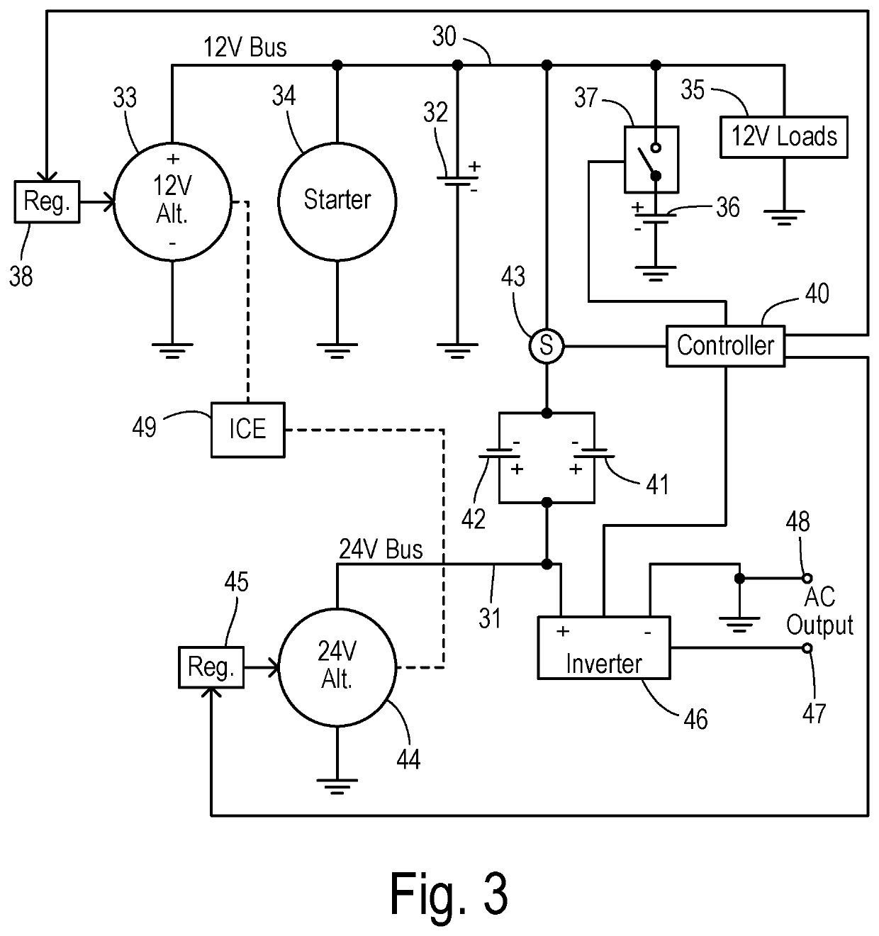
[0031]In a first embodiment, a voltage set point for the 24-volt alternator is set according to a formula:

BattULoChrg_U_Cmd_24V=BattULoChrg_U_Cmd+VBatt_FloatChg12V

where BattULoChrg_U_Cmd_24V is the voltage set point for 24-volt alternator, and where VBatt_FloatChg12V is a floating charging voltage for a 12-volt battery (which is about 13V at room temperature and is adjusted according to battery temperature).

second embodiment

[0032]In a second embodiment, the voltage set point for the 24-volt alternator is adjusted in a manner that optimizes performance with respect to use of the SRC function. When the vehicle is decelerated using the brake pedal, the combustion engine consumes little or no fuel and the alternator can be used to brake the vehicle. In this condition, output electric power from the alternator can convert “braking energy” of the vehicle to a battery charging current without consuming fuel. In this condition, the alternator output voltage is preferably adjusted higher so that the batteries can be charged using a larger current.

[0033]During vehicle acceleration, the efficiency of the combustion engine is lower than normal. In this condition, the alternator voltage is preferably adjusted to be lower than the battery voltage so that the power net will be supported by the corresponding batteries and the alternator load on the combustion engine is reduced during the acceleration.

[0034]Accordingly...


PUM


Abstract

A vehicle operates an internal combustion engine according to an automatic start-stop function to reduce fuel consumption. A first DC bus is adapted to connect to a plurality of DC loads. A primary battery is coupled between the first DC bus and a ground. A first alternator is driven by the internal combustion engine to supply electrical power to the first DC bus. A second DC bus is connected to a positive terminal of an auxiliary battery. A negative terminal of the auxiliary battery is connected to the first DC bus. A second alternator is driven by the internal combustion engine to supply electrical power to the second bus at a voltage corresponding to a sum of voltages of the primary and auxiliary batteries. An inverter receives electrical power from the second DC bus to generate an AC output adapted to connect to accessory AC loads.

Description

CROSS REFERENCE TO RELATED APPLICATIONS[0001]Not Applicable.STATEMENT REGARDING FEDERALLY SPONSORED RESEARCH[0002]Not Applicable.BACKGROUND OF THE INVENTION[0003]The present invention relates in general to motor vehicle electrical systems, and, more specifically, to an electrical architecture having a low voltage bus for powering typical DC loads and a higher voltage bus for powering a DC / AC inverter supporting AC loads.[0004]Cars, trucks, and other motor vehicles driven by internal combustion engines have typically employed an electrical system based on a DC voltage at about 12 volts. The DC power is derived from a storage battery (nominally at 12V) and an alternator. The alternator is driven by the engine and controlled by a voltage regulator that varies the alternator output to recharge the battery and maintain a desired voltage on a DC bus that connects to various DC loads including a starter motor.[0005]In order to facilitate the connection of portable electric devices, vehicle...

Claims


Application Information

Patent Timeline
IPC IPC(8): H02J7/14H02M7/5375H02M7/48B60L50/14F02N11/08
CPCF02N11/0814H02M7/4826H02J7/1423B60L50/14H02M7/5375H02J7/1438B60L2210/40B60R16/03H02J3/38F02N11/04F02N11/0825F02N11/0866F02N2011/0896F02N2200/062H02J7/143H02J2310/46Y02T10/40
Inventor CHEN, HANYANG B.IRBY, MICHAEL J.JUDGE, ALAN F.SPOTO, ANTHONY T.SALTER, STUART C.BAKER, JASON
Owner FORD GLOBAL TECH LLC
Why Eureka
Try Eureka