
Method for manufacturing shunt resistor

a technology of shunt resistor and manufacturing method, which is applied in the direction of resistor details, manufacturing tools, welding apparatus, etc., can solve the problems of increasing welding cost, poor appearance of shunt resistor, and poor control of shunt resistor resistance, so as to increase the resistance of materials

Active Publication Date: 2020-10-27
YAGEO CORP
View PDF19 Cites 0 Cited by
  • Summary
  • Abstract
  • Description
  • Claims
  • Application Information

AI Technical Summary

Benefits of technology

This approach reduces production costs, increases productivity, and enhances the accuracy and stability of shunt resistors by centering heat and current on the rivets for efficient welding, allowing for continuous manufacturing and improved material utilization.

Problems solved by technology

However, an E-beam welding operation has to be performed in vacuum for the whole process, thus increasing welding cost.
In addition, during the E-beam welding operation, materials are likely to be spattered, thus not only affecting a main body of the resistance alloy material that results in a bad control on the resistance of the shunt resistor, but also forming holes and / or spattered protrusions on a surface of the shunt resistor that results in a poor appearance of the shunt resistor.
Furthermore, if the depth of the E-beam is not appropriately adjusted during welding, obvious weld beads are formed, and the resistance of the shunt resistor is also hard to be controlled.
Accordingly, it needs a lot time to trim the resistance of the shunt resistor that is formed by using the E-beam welding technique.
A remnant of the resistance composite material after being punched is a composite material of the electrode material and the resistance alloy material, and thus is difficult to be recycled.
When being aligned and emitted toward top and bottom sides of the resistance composite material for welding the resistance composite material, the laser beams are often too large or too small, thus resulting in weld beads with poor appearance, and poor control of the resistance of the shunt resistor.
In addition, the laser beam welding technique also has disadvantages including of difficultly recycling remnants of the material and requiring a lot time of trimming the resistance.

Method used


Image

  • Method for manufacturing shunt resistor
  • Method for manufacturing shunt resistor
  • Method for manufacturing shunt resistor

Examples


Embodiment Construction

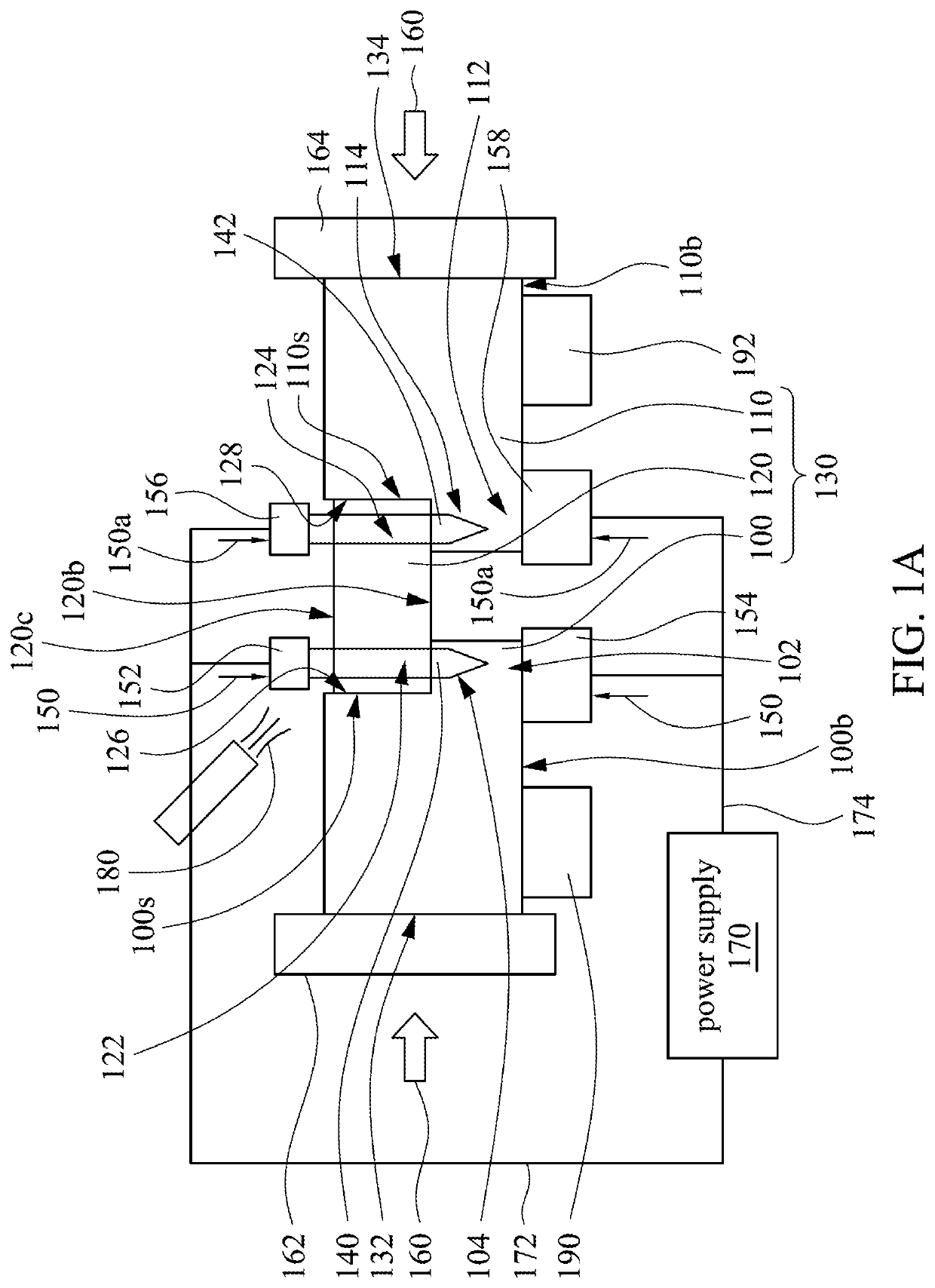
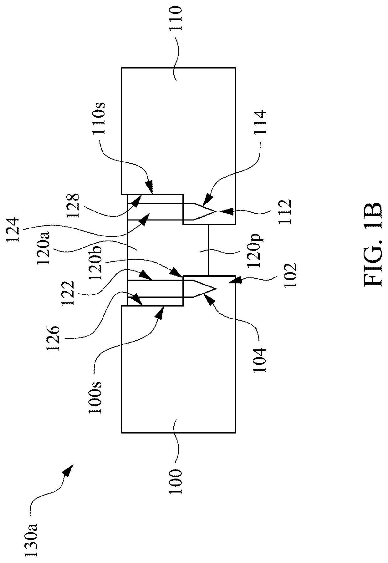
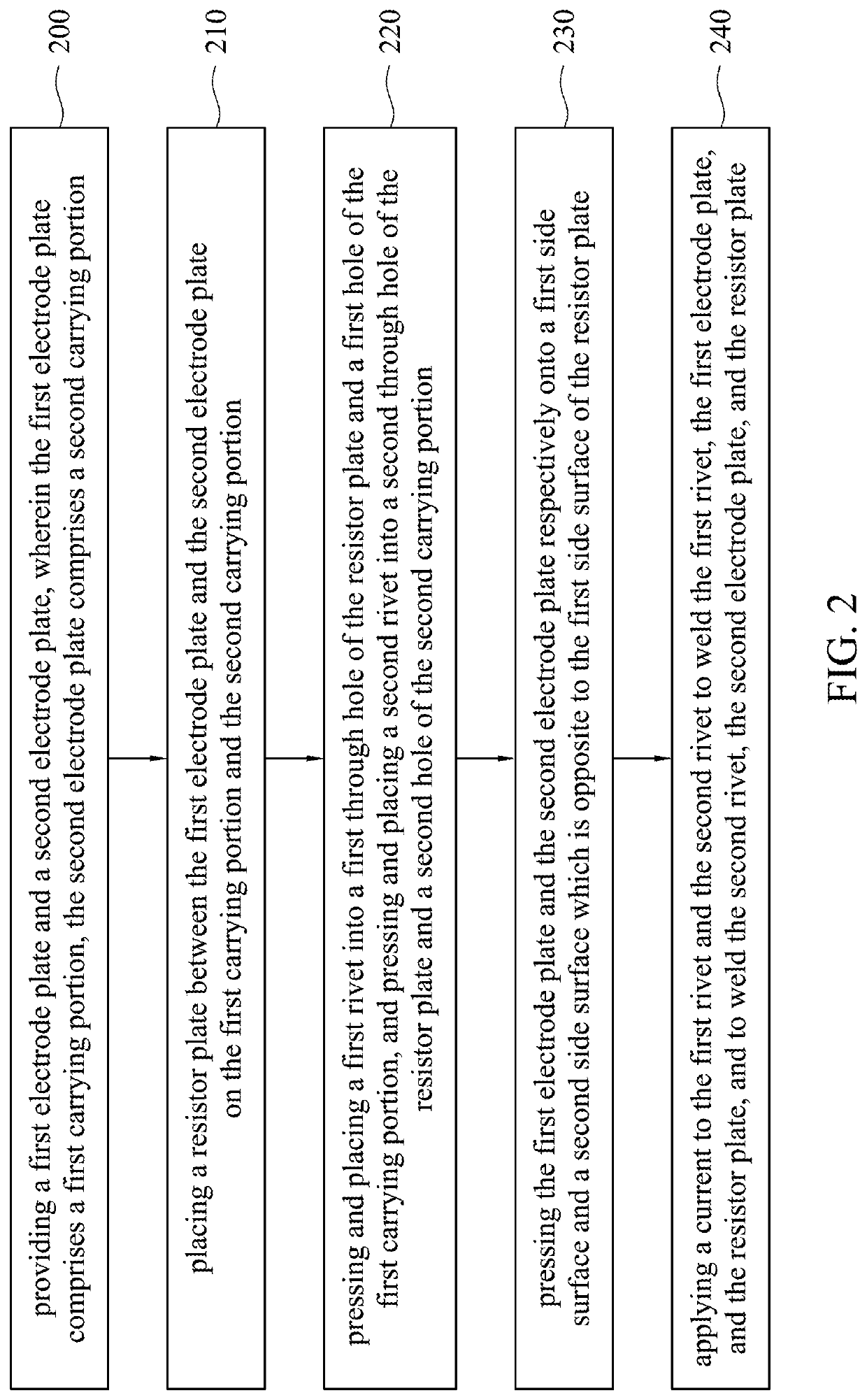
[0018]Referring to FIG. 1A and FIG. 2, FIG. 1A is a schematic diagram of an installation for manufacturing a shunt resistor in accordance with a first embodiment of the present invention, and FIG. 2 is a flow chart of a method for manufacturing a shunt resistor in accordance with the first embodiment of this invention. In the present embodiment, in manufacturing a shunt resistor, a step 200 is firstly performed to provide a first electrode plate 100 and a second electrode plate 110. The first electrode plate 100 includes a first carrying portion 102, in which the first carrying portion 102 protrudes from a side surface 100s of the first electrode plate 100. The second electrode plate 110 includes a second carrying portion 112, in which the second carrying portion 112 protrudes from a side surface 110s of the second electrode plate 110. In the other embodiments, the first electrode plate 100 and the second electrode plate 110 may include stepped structures. The first electrode plate ...


PUM

PropertyMeasurementUnit
melting pointsaaaaaaaaaa
pressureaaaaaaaaaa
currentaaaaaaaaaa

Abstract

A method for manufacturing a shunt resistor is described. In this method, a first electrode plate and a second electrode plate are provided. The first electrode plate includes a first carrying portion having a first hole. The second electrode plate includes a second carrying portion having a second hole. A resistor plate is placed between the first and second electrode plates. The resistor plate has a first through hole and a second through hole respectively on the first hole and the second hole. A first rivet is pressed into the first through hole and the first hole. A second rivet is pressed into the second through hole and the second hole. Current is applied to the first rivet and the second rivet to weld the first rivet, the first electrode plate and the resistor plate, and to weld the second rivet, the second electrode plate and the resistor plate.

Description

RELATED APPLICATIONS[0001]This application claims priority to China Application Serial Number 201810251026.1, filed Mar. 26, 2018, which is herein incorporated by reference.BACKGROUNDField of Invention[0002]The present invention relates to a resistor. More particularly, the present invention relates to a method for manufacturing a shunt resistor having a modular structure.Description of Related Art[0003]In manufacturing a shunt resistor, an E-beam welding technique, a seam welding technique or a laser beam welding technique is typically used to combine a highly electrically-conductive electrode material with a resistance alloy material to form a resistance composite material. Then, the resistance composite material is divided and punched to form a preliminary model for plural shunt resistors. Next, resistance of the preliminary model of the shunt resistor is trimmed and adjusted by using a resistance trimming apparatus, so as to achieve an accuracy of the resistance of the shunt res...

Claims


Application Information

Patent Timeline
Patent Type & Authority Patents(United States)
IPC IPC(8): B23K11/00B23K3/03H01C1/144H01C17/28
CPCB23K3/0307H01C1/144B23K11/0066H01C17/28H01C17/00
Inventor HSIAO, SHEN-LILIN, KUANG-CHENGLEE, HWAN-WENCHEN, CHIH-LUNG
Owner YAGEO CORP
Learn More