
Aircraft heating arrangement

a technology for heating arrangements and aircraft, applied in the field of aircraft heating arrangements, can solve the problems of increasing the pressure of the air, requiring even larger and more powerful fans, and complicated air heating systems, and achieves the effect of high resistance and high resistance material

Active Publication Date: 2011-10-27
ELECTROFILM MFG
View PDF1 Cites 0 Cited by
  • Summary
  • Abstract
  • Description
  • Claims
  • Application Information

AI Technical Summary

Benefits of technology

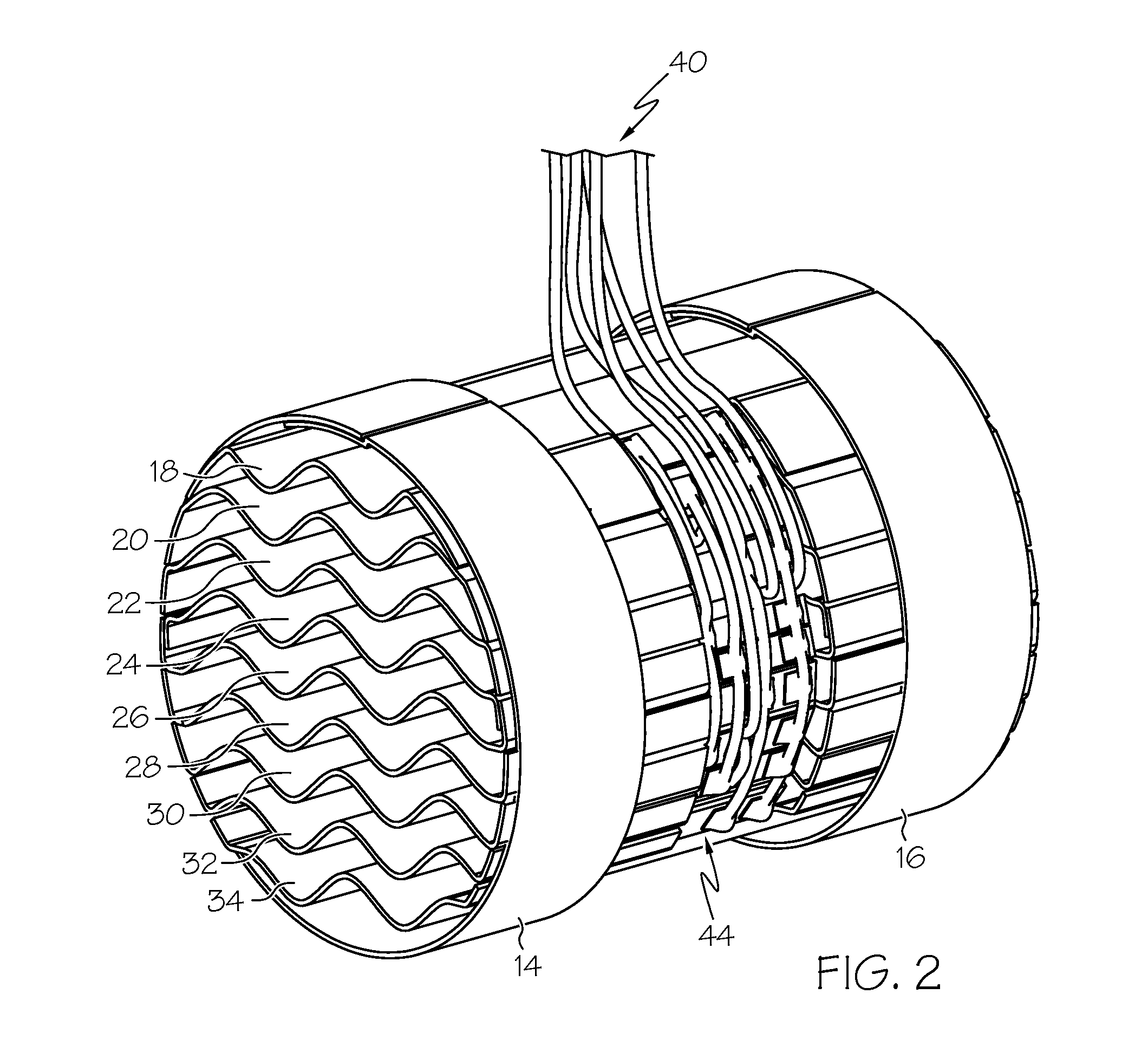
[0010]A heater for heating air passing through a conduit to an aircraft cabin includes a support in the conduit, defining an air passage there through. A plurality of corrugated heating elements is provided. Each heating element extends across the air passage and is supported only by the support at the periphery of the air passage. The corrugated heating elements are generally evenly spaced in the air passage. A power supply provides electrical current to the heating elements such that air passing through the air passage is heated. Each of the plurality of corrugated heating elements defines a plurality of parallel and alternating ridges and grooves. The ridges and grooves extend generally in the direction of air flow through the air passage. The power supply includes a thermal sensor in the air passage adjacent the end of the heater from which the heated air exits. The thermal sensor provides an indication of the temperature of the heated air. The thermal sensor may include a bimetal element for controlling the application of power to the heating elements such that the air adjacent the thermal sensor is maintained within temperature limits. The power supply may include a resistance sensor for sensing the electrical resistance of one or more of the heater elements. The resistance provides an indication of the temperature of the heating element. The heating elements may be made of a high resistance material laminated between non-conductive layers, and the high resistance material may be a nickel chromium alloy. Three phase electrical current may be provided to the plurality of heating elements. Alternatively, the heating elements may be connected to single phase or two phase power sources. The non-planar heating elements are sufficiently robust so as not to require support within the air passage as a consequence of their non-planar shapes.

Problems solved by technology

Such devices complicate the air heating system, and produce an additional drop in the pressure of the air, requiring even larger and more powerful fans.
However, unless the flat heating elements are reinforced with additional materials, or supported with secondary internal structures that adversely reduce the airflow area, these flat components have been found to be too weak to withstand the vibration to which aircraft heaters are subjected in normal operation.
Incorporating support structures into the interior of such a heater, however, has resulted in restricting the flow of air through the heater, causing a greater pressure drop and more uneven heating.
An additional drawback of using thin, flat heating elements is that they may produce an air flow pattern that switches sporadically between laminar and turbulent flow under minor variations in air flow rate.
This change between laminar and turbulent flow reduces heater efficiency, and can also cause damage to the heater due to overheating of portions of the heater elements.

Method used


Image

  • Aircraft heating arrangement
  • Aircraft heating arrangement
  • Aircraft heating arrangement

Examples


Embodiment Construction

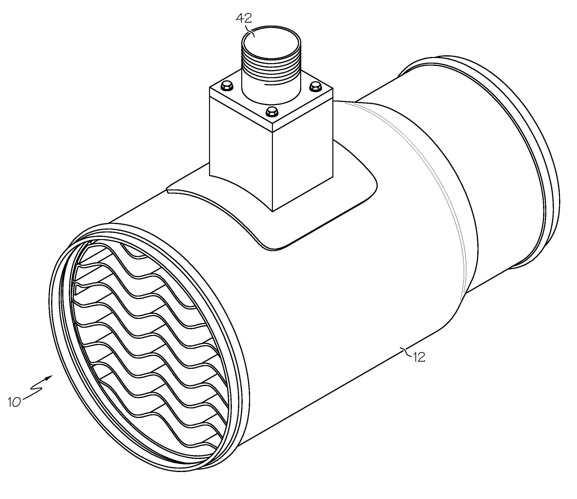
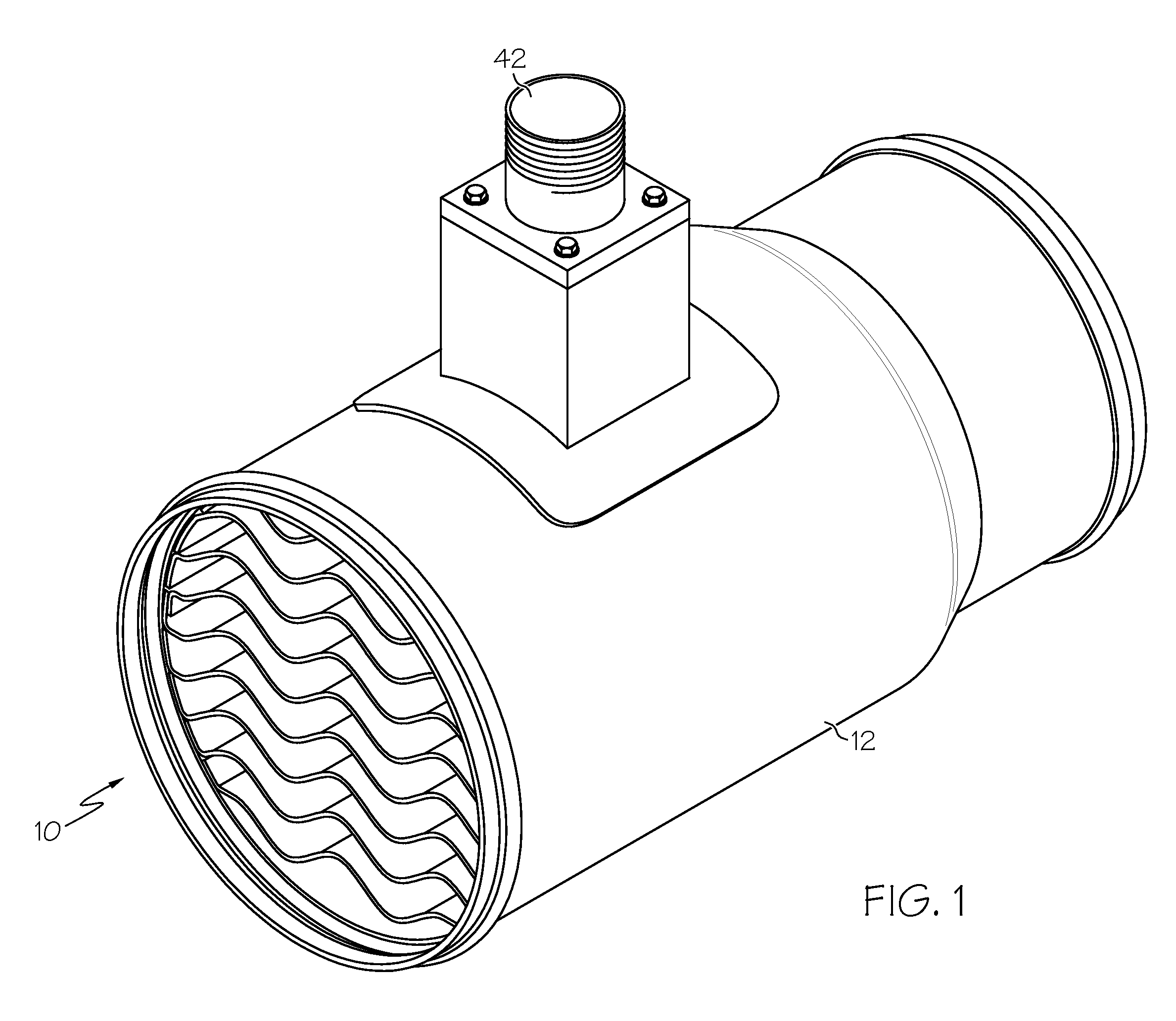
[0016]FIG. 1 shows a heater 10 for heating air passing through a conduit 12 to an aircraft cabin. This air may come from outside the aircraft, from inside the aircraft, or from both. As seen more clearly in FIGS. 2-4, the heater includes first and second support rings 14 and 16. Each of the support rings 14 and 16 is generally annular in shape and defines an air passage there through. The rings 14 and 16 are each made of an electrically non-conductive material so that a plurality of serpentine heating elements 18, 20, 22, 24, 26, 28, 30, 32, and 34 can be supported by the support rings 14 and 16, with the heating elements being electrically isolated from each other and from other heater components. The heating elements are each made of a high electrical resistance material that is laminated between non-conductive layers. The high resistance material may be a nickel chromium alloy, such as for example Iconel high resistivity alloy. Each of the heating elements 18-34 extends across th...


PUM


Abstract

A heater for heating air passing through a conduit to an aircraft cabin includes a first support ring in the conduit, defining an air passage there through. A plurality of serpentine heating elements is provided, with each heating element extending across the air passage and being supported at both sides of the air passage by the support ring. The serpentine heating elements are generally parallel to each other and evenly spaced in the air passage. A power supply supplies electrical current to the heating elements such that air passing through the air passage is heated by the heating elements. The heating elements may are non-planar, wavy, corrugated in shape, permitting them to be supported only at their side edges.

Description

CROSS-REFERENCE TO RELATED APPLICATION[0001]This application claims the benefit of U.S. Provisional Application Ser. No. 61 / 328,351, filed on Apr. 27, 2010, for APPARATUS FOR IMPROVING SUPPLEMENTAL AIRCRAFT ELECTRICAL HEATING.STATEMENT REGARDING FEDERALLY SPONSORED RESEARCH OR DEVELOPMENT[0002]Not applicable.BACKGROUND OF THE INVENTION[0003]Aircraft are typically equipped with electrical air heaters that heat air supplied through an air duct to one or more exit registers in the cabin interior. The air to be heated may be drawn from outside of the aircraft, recirculated cabin air, or a mixture of outside air and cabin air, and the heater may typically raise the temperature of the air by approximately 45° F. The flow of air through the heater can be produced by either a remote, electrically powered fan, or by a fan positioned immediately adjacent the heater. Such a heater typically has heating elements that are enclosed within a protective, electrically non-conductive shell to prevent...

Claims


Application Information

Patent Timeline
Patent Type & Authority Applications(United States)
IPC IPC(8): B60L1/00
CPCB60L1/02
Inventor SANDIFORD, ARTHUR DAVID
Owner ELECTROFILM MFG
Learn More