
Combustion burner

a burner and combustion technology, applied in the field of combustion burners, can solve the problems of high turbulence and foaming, rapid melting of glass batches, and inability to fabricate the entire burner using these materials, and achieve the effect of reducing or eliminating problems

Active Publication Date: 2020-12-08
JOHNS MANVILLE CORP
View PDF319 Cites 0 Cited by
  • Summary
  • Abstract
  • Description
  • Claims
  • Application Information

AI Technical Summary

Benefits of technology

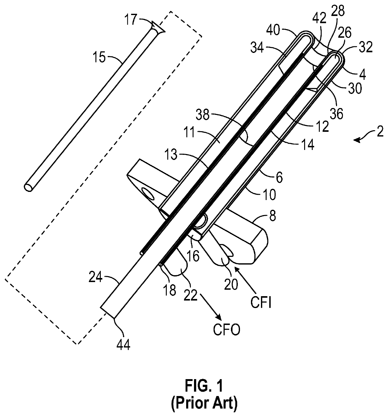
[0007]In accordance with the present disclosure, submerged combustion (SC) burners are described that may reduce or eliminate problems with known SC burners, melters, and methods of using the melters to produce molten glass.

Problems solved by technology

The introduction of high flow rates of products of combustion of the oxidant and fuel into the molten glass, and the expansion of the gases during submerged combustion (SC), cause rapid melting of the glass batch and much turbulence and foaming.
However, being expensive alloys, it is not presently economical to fabricate the entire burner using these materials.

Method used


Image

  • Combustion burner
  • Combustion burner
  • Combustion burner

Examples


embodiment 100

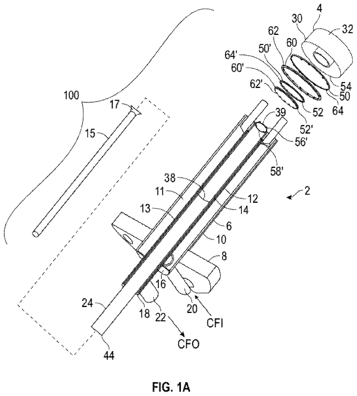
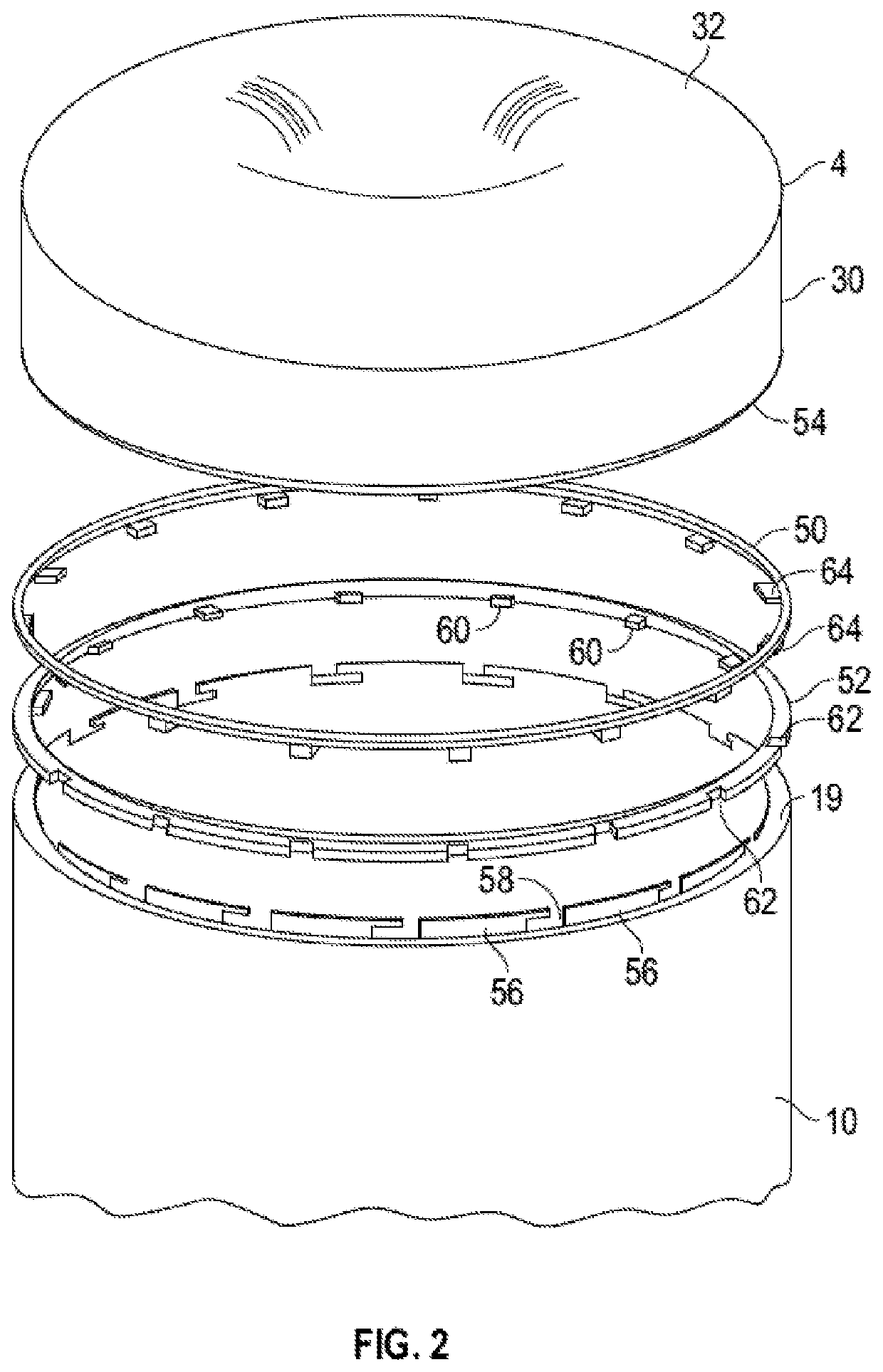
[0065]Referring now again to the figures, FIG. 1A is an exploded perspective view of one non-limiting embodiment 100 in accordance with the present disclosure, illustrating a first ring 50 and a second ring 52 for forming an outer connection. While the term “ring” is used, it will be understood that this is simply used for simplicity, and that other shaped members may be employed. First ring 50 interference fits onto a shaped end 54 of outer wall 30 of burner tip 4, while second ring 52 interference fits onto a shaped first end 19 of external conduit 10. It will readily be understood that similar rings may be used for forming an inner connection between inner wall 28 of burner tip 4 and second internal conduit 14. These rings may be referred to herein as third and fourth rings 50′, 52′.

[0066]Referring again to FIG. 1A as well as FIG. 2, first ring 50 may include a plurality of mating projections 64 which mate with a corresponding plurality of circumferentially spaced, outward openin...

embodiment 300

[0081]Methods of making a fluid-cooled submerged combustion burner using interference fittings are considered another aspect of the present disclosure. As illustrated in FIG. 10, one method embodiment 300 may include the steps of:[0082](a) forming a first interference fitting of a first ring (50) to a shaped end (54) of an outer wall (30) of a burner tip (4) by:[0083](i) adjusting temperatures of the first ring (50) and burner tip (4) to cause relative diameters of the first ring (50) and shaped end (54) to change so that first ring (50) fits around shaped end (54), the first ring (50) having a smaller initial diameter than the shaped end (54) of the outer wall (30) of the burner tip (4),[0084](ii) placing the first ring (50) in position adjacent the shaped end (54) of the outer wall (30), and[0085](iii) adjusting temperatures of the first ring (50) and shaped end (54) to form the first interference fit (box 302);[0086](b) forming a second interference fitting of a second ring (52) ...


PUM

PropertyMeasurementUnit
melting temperaturesaaaaaaaaaa
melting pointsaaaaaaaaaa

Abstract

Submerged combustion burners having a burner body and a burner tip connected thereto. The burner body has an external conduit and first and second internal conduits substantially concentric therewith, forming first and second annuli for passing a cooling fluid therethrough. The burner includes a generally central flow passage for a combustible mixture, the flow passage partially defined by an inner wall of the burner tip. The burner tip has an outer wall and crown connecting the inner and outer walls. The inner and outer walls and crown comprise materials having greater corrosion and / or fatigue resistance than the burner external conduit. The burner tip is connected to the burner body by inner and outer connections, at least one of which includes members interference fit to the burner tip and burner body, the members welded, soldered, or brazed together, in certain instances by fiber laser welding.

Description

BACKGROUND INFORMATION[0001]Technical Field[0002]The present disclosure relates generally to the field of combustion burners and methods of use, and more specifically to burners, methods of their manufacture, submerged combustion melters, and methods of their use, particularly for melting glass-forming materials.[0003]Background Art[0004]A submerged combustion melter (SCM) may be employed to melt glass batch and / or waste glass materials to produce molten glass by passing oxygen, oxygen-enriched mixtures, or air along with a liquid, gaseous and / or particulate fuel (some of which may be in the glass-forming materials), directly into a molten pool of glass, usually through burners submerged in a glass melt pool. The introduction of high flow rates of products of combustion of the oxidant and fuel into the molten glass, and the expansion of the gases during submerged combustion (SC), cause rapid melting of the glass batch and much turbulence and foaming.[0005]In the context of SCMs, SC ...

Claims


Application Information

Patent Timeline
Patent Type & Authority Patents(United States)
IPC IPC(8): C03B5/23C03B5/235F23D14/78
CPCF23D14/78C03B5/2356C03B2211/22F23D2214/00F23D2900/00018F23D14/76F23C3/004
Inventor RICHARDSON, III, MORRIS L.
Owner JOHNS MANVILLE CORP
Learn More