Rotor for a reluctance machine

a reluctance machine and rotor technology, applied in the direction of synchronous motors, magnetic circuit rotating parts, magnetic circuit shape/form/construction, etc., can solve the problems of machine being very heavy, parts of the rotor being subjected to significant centrifugal forces, etc., to improve the weight and efficiency of the reluctance machine

Active Publication Date: 2020-12-08
SIEMENS AG
View PDF20 Cites 0 Cited by
  • Summary
  • Abstract
  • Description
  • Claims
  • Application Information

AI Technical Summary

Benefits of technology

[0005]Against this background, the object of the invention is to improve the weight and the efficiency of a reluctance machine, in particular a synchronous reluctance machine. The object is achieved by a rotor according to claim 1 and by a production method according to claim 8.
[0010]It is specifically possible to combine different additive manufacturing methods with each other. It is also possible when using a manufacturing method, for example, to employ nozzles etc. of different sizes in order to efficiently produce structures of different sizes.
[0011]As a result of using such additive manufacturing methods, it is firstly possible to produce almost any desired three-dimensional shapes, which cannot be produced or can only be produced at disproportionately high expense using conventional deformation, cutting and joining methods. In particular, the size of the structures generated is almost unlimited. Limitations are predefined if necessary by the diameter of a laser beam or an electron beam which is used for melting, or by the diameter of a particle stream that is emitted by a nozzle. It is also possible in this way to join magnetic-flux-conducting and non-magnetic-flux-conducting materials together in almost any desired manner (possibly using an intermediate layer). Since the process-related limitations of the stamping process no longer apply, the weight of the rotor can be significantly reduced. In particular, as described below, structures which were comparatively difficult to create from electric steel sheet in the prior art can be made from insulating materials which are comparatively light. In addition to the weight advantage, which when using a rotor naturally also increases the efficiency of the reluctance machine due to the reduced moment of inertia, the selective use of insulating materials and / or the omission or thinning of specific structures made of conductive material allows stray fluxes to be reduced, which again has a positive effect on the efficiency.
[0015]Such an in-layer insulating rib is preferably also electrically insulating. The designation “in-layer insulating rib” signifies in this context that it extends between two conductor regions within a conductor layer. The in-layer insulating rib is generated by means of an additive manufacturing method, which offers the widest range of possibilities in respect of its dimensions and geometry. It is obviously also possible for a plurality of in-layer insulating ribs to be arranged between and connect two conductor regions. Each insulating rib connects the adjoining conductor regions mechanically and therefore improves the mechanical stability of the rotor. At the same time, such a rib of non-magnetic-flux-conducting material does not cause any unwanted stray fluxes, which do occur when using connecting ribs made of steel sheet as per the prior art. Moreover, many non-magnetic-flux-conducting materials are characterized by a lesser thickness than e.g. electric steel sheet, and therefore the weight and the moment of inertia of the rotor can be reduced in comparison with the prior art. This is further assisted by the fact that, due to the nature of the manufacturing, the rib need not be embodied any thicker than is absolutely necessary for the mechanical stability.
[0022]The geometry of the intermediate insulating ribs can also be varied considerably. For example, an intermediate insulating rib can run perpendicularly or obliquely relative to the directional course of the conductor layers. An intermediate insulating rib can also have a variable cross section. For example, it may have a larger cross section in the connecting regions to the conductor layers, in order to allow better attachment, while having a smaller cross section in an intermediate central section. The insulating rib can also be curved and / or angled. Furthermore, the insulating rib can be cut through or two insulating ribs can intersect each other, e.g. in the shape of an X or V. The mechanical oscillatory characteristics of the rotor can be influenced inter alia by the geometry of the intermediate insulating ribs and in-layer insulating ribs, such that unwanted noise development can be prevented if applicable.

Problems solved by technology

These and other manufacturing limitations are caused inter alia by the requirement to stamp the laminations.
While the use of stamped laminations allows the rotor to be produced in a proven and relatively economical manner, the machine is consequently very heavy.
This means that parts of the rotor may be subjected to significant centrifugal forces depending on rotational speed.
However, this results in unwanted stray fluxes which reduce the effectiveness of the machine.

Method used


Image

  • Rotor for a reluctance machine
  • Rotor for a reluctance machine
  • Rotor for a reluctance machine

Examples


second embodiment

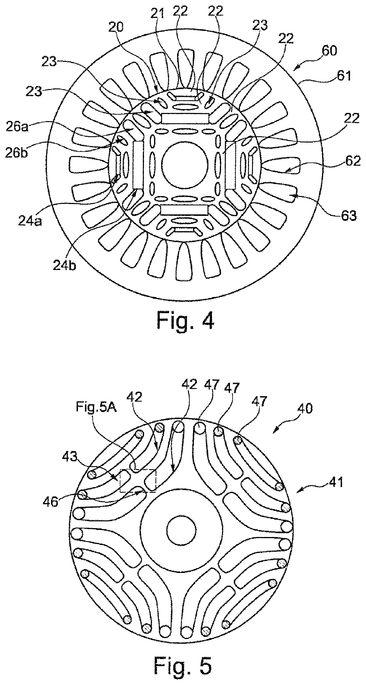
[0050]FIG. 4 shows an illustration of a second embodiment variant of a rotor 20 and a stator 60. Shown again in this context is a transverse section relative to the axial direction A, including a conductor layer 61 of the stator 60 and a conductor layer 21 of the rotor 20. The conductor layer 61 of the stator has a plurality of gaps 63 which are arranged in a continuous circle with ribs 62 between them. The ribs 62 are made of magnetic-flux-conducting material here. The conductor layer 61 can be made of stamped steel sheet if applicable or it can be produced in an additive manufacturing method, whereby finer structures can be realized if applicable. The conductor layer 21 of the rotor 20 comprises various conductor regions 22 and insulation regions 23 which are arranged between them. In-layer insulating ribs 24a, 24b are arranged in some insulation regions 23, having been built up from a non-magnetic-flux-conducting material during the course of the additive manufacturing. It is als...

third embodiment

[0051]FIG. 5 shows a third embodiment variant of a rotor 40, only one conductor layer 41 being illustrated again. It is possible here likewise to identify conductor regions 42 and insulation regions 43 arranged between them. The insulation regions 43 may be completely filled with air or in-layer insulating ribs may be sectionally present, though this is not shown here. Furthermore, the conductor regions 42 are partially connected by conductor ribs 46 which extend transversely relative to the directional course of the respective conductor regions 42. The conductor regions 42 and the conductor ribs 46 were produced from two different magnetic-flux-conducting materials in an additive manufacturing method. As shown in FIG. 5A, which represents a magnified detail view of FIG. 5, both the conductor regions 42 and the conductor ribs consist predominantly of a first magnetic-flux-conducting material, in which strips 45 of a second magnetic-flux-conducting material are however embedded. The ...

fourth embodiment

[0053]FIG. 6 shows a fourth embodiment variant of a rotor 50, a conductor layer 51 being illustrated here likewise. This is a variant of the embodiment from FIG. 2, having conductor regions 52 and insulation regions 53 of essentially corresponding design. However, bars 57 of a squirrel-cage winding are attached to the conductor regions 52 at a radially outer side, and are adapted to the shape of the conductor regions 52 in respect of their cross section. In this case, it is obviously advantageous to build up the bars 57 concurrently with the conductor regions 52 and the insulation regions 53 by means of additive manufacturing.


PUM


Abstract

A rotor for a reluctance machine includes conductor layers and insulation layers arranged in alternation in the axial direction. The conductor layers have magnetic-flux-conducting conductor regions and the insulation layers are electrically insulating. To improve weight and efficiency of a reluctance machine, the rotor is produced at least partially by additive manufacturing.

Description

CROSS-REFERENCES TO RELATED APPLICATIONS[0001]This application is the U.S. National Stage of International Application No. PCT / EP2017 / 057647, filed Mar. 31, 2017, which designated the United States and has been published as International Publication No, WO 2017 / 211477 and which claims the priority of European Patent Application, Serial No. 16173304.3, filed Jun. 7, 2016, pursuant to 35 U.S.C. 119(a)-(d).BACKGROUND OF THE INVENTION[0002]The invention relates to a rotor for a reluctance machine and to a corresponding production method.[0003]In reluctance machines, a stator conventionally generates an alternating magnetic field by means of which a rotor is driven, essentially as a result of the reluctance force. In this context, both the rotor and the stator usually have cores of axially stacked laminations which are insulated from each other by varnish layers on one side. The laminations consist of a material having high magnetic permeability, e.g. electric steel sheet. Each laminatio...

Claims


Application Information

Patent Timeline
Patent Type & Authority Patents(United States)
IPC IPC(8): H02K1/24H02K15/02H02K19/10H02K19/20
CPCH02K19/20H02K15/02H02K1/246H02K19/103B33Y10/00B33Y80/00
Inventor BITTNER, ROLANDHÖSLE, MARKUS
Owner SIEMENS AG
Why Eureka
Try Eureka