Electric work machine

a work machine and work shaft technology, applied in windings, agriculture tools and machines, magnetic circuit shapes/forms/construction, etc., can solve the problems of low alignment accuracy and difficulty in high reliability lockout, and achieve high output power, increase space efficiency, and reduce the weight and size of the stator

Active Publication Date: 2020-12-08
MAKITA CORP
View PDF8 Cites 0 Cited by
  • Summary
  • Abstract
  • Description
  • Claims
  • Application Information

AI Technical Summary

Benefits of technology

[0006]The method described in Patent Literature 2 cannot reduce the wire diameter any further to produce the same output power when more coils are to be connected in parallel. The coils of the three phases are connected to one another with the connecting wire between the coils routed back and forth between the connecting side of the stator and the opposite side. The connecting wire may be routed in a complex manner depending on the series and parallel arrangements of the coils. The connecting wire may be crossed to have crossing portions that may contact each other and wear under vibrations.
[0043]The structures according to the fourth and fifth aspects allow use of a wire with a smaller diameter than in a star connection to achieve the same output power, and allow use of thinner winding nozzles in a star connection. These structures increase space efficiency, and achieve high output power. More specifically, these structures reduce the weight and the size of the stator.

Problems solved by technology

The stator locked not to rotate at the insulator as described in Patent Literature 1 may have low alignment accuracy due to tolerances.
Also, the stator is locked with the degree of reliability dependent on the strength of the resin insulator, and is thus difficult to lock with high reliability.

Method used


Image

  • Electric work machine
  • Electric work machine
  • Electric work machine

Examples


Embodiment Construction

[0062]An electric work machine according to an embodiment will now be described with reference to the drawings.

Lawn Mower

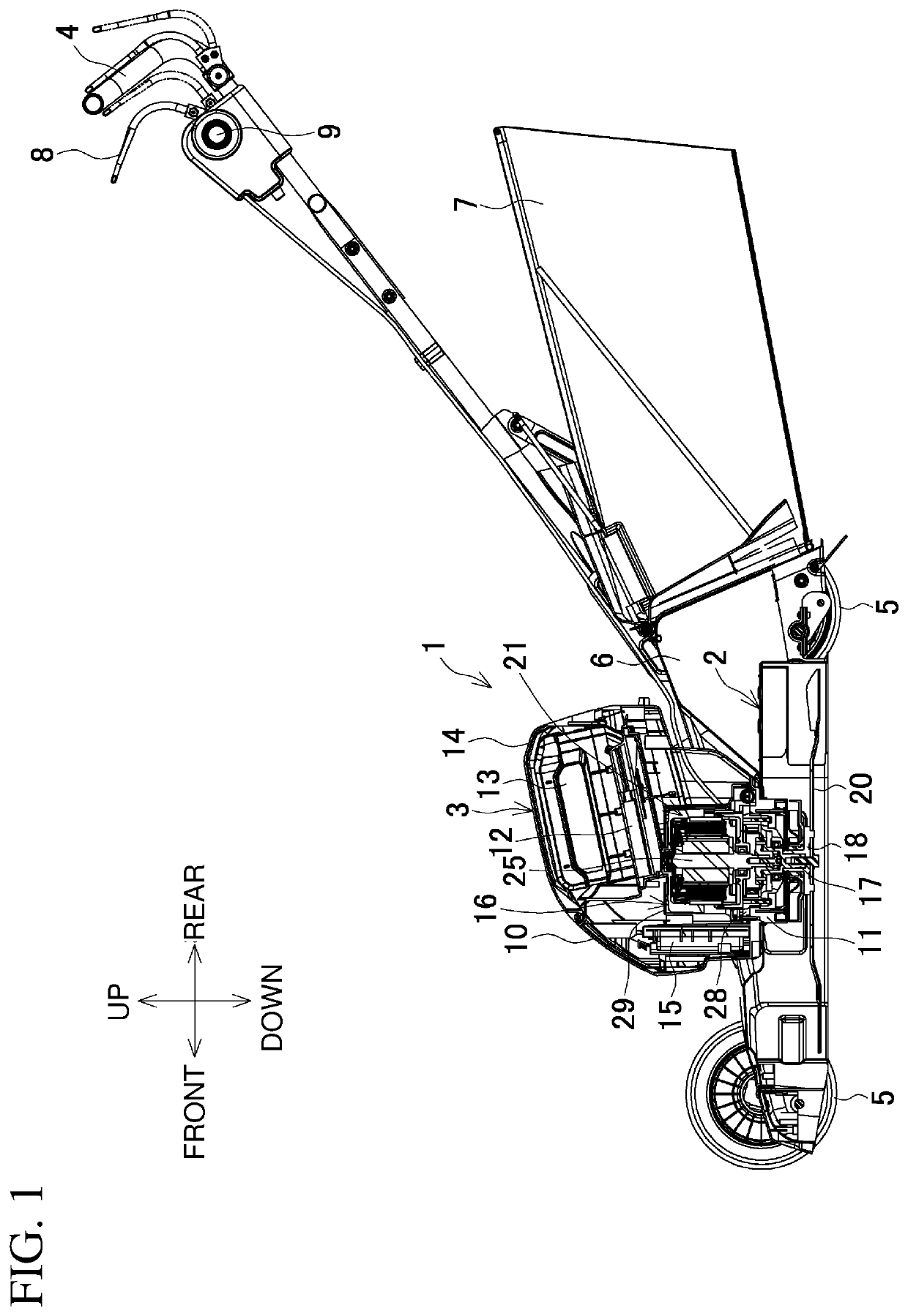
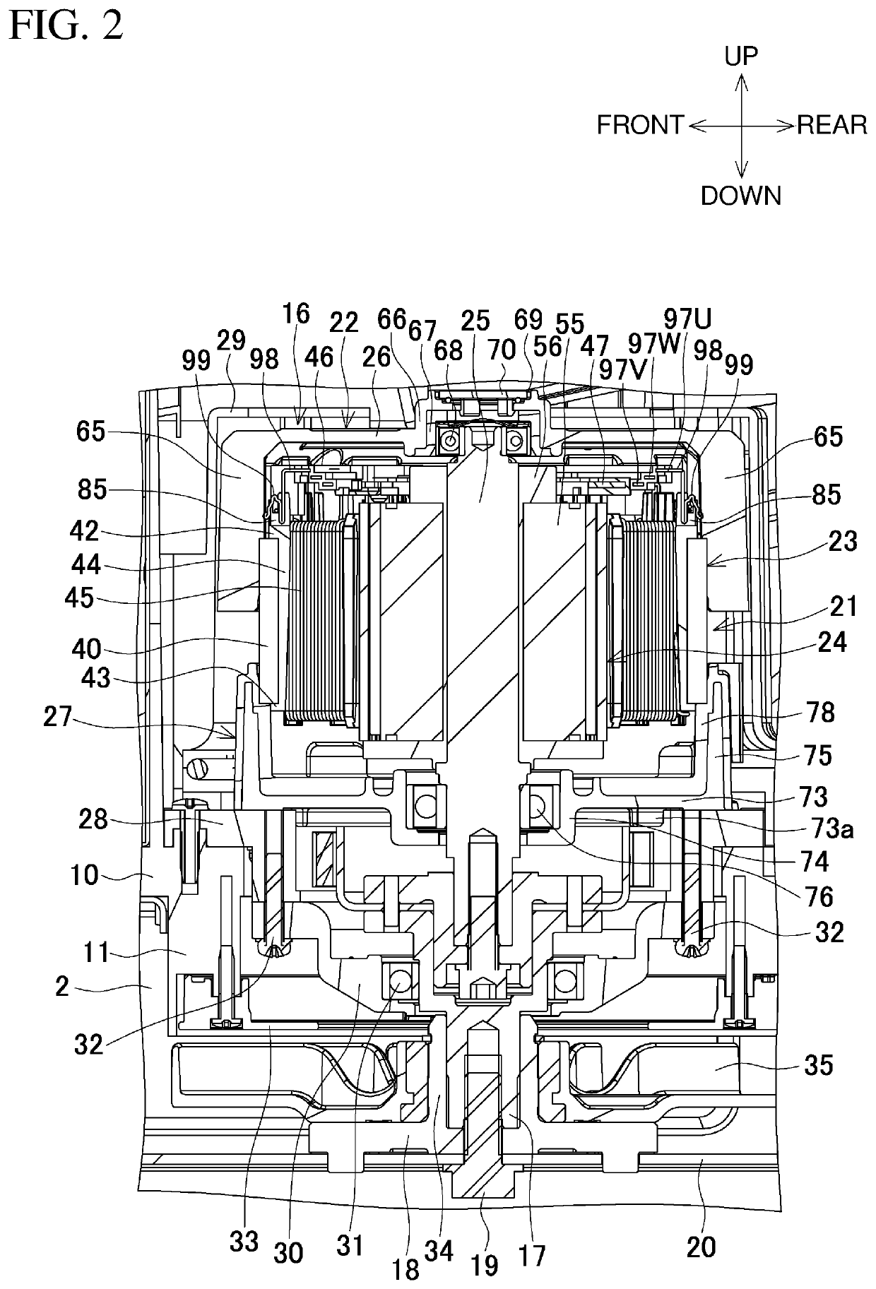
[0063]FIG. 1 is a longitudinal central sectional view of a rechargeable lawn mower as an example of an electric work machine. FIG. 2 is an enlarged view of a part including a motor unit.

[0064]The lawn mower 1 includes a base 2, a body 3, and a handle 4. The base 2 extends in the front-rear direction, and has an opening in its lower surface. The body 3 is coupled to a central area of the upper side of the base 2. The handle 4 extends obliquely upward from the base 2 toward the rear.

[0065]The base 2 includes a pair of front wheels 5 and a pair of rear wheels 5. The base 2 is movable back and forth with the handle 4. Behind the base 2, a rear cover 6 and a grass bag 7 are located under the handle 4. The handle 4 has a switch lever 8 on the rear end. The handle 4 has a lock-off button 9 in front of the switch lever 8 to lock the operation of the switch lever 8 in a no...


PUM


Abstract

An electric work machine includes a brushless motor including a stator including a stator core, an electrical insulator located on the stator core, and at least one coil wound around the stator core with the electrical insulator in between, and a rotor rotatable with respect to the stator, and an output unit drivable by the brushless motor. The stator core has a through-hole and / or a recess to lock rotation of the stator with a screw.

Description

CROSS-REFERENCE TO RELATED APPLICATIONS[0001]This application claims the benefit of priority to Japanese Patent Application No. 2018-148703, filed on Aug. 7, 2018, and Japanese Patent Application No. 2018-148704, filed on Aug. 7, 2018, the entire contents of which are hereby incorporated by reference.BACKGROUND1. Technical Field[0002]The present invention relates to an electric work machine including a power tool, a gardening tool such as a lawn mower, and an air compressor for an air tool.2. Description of the Background[0003]An electric work machine such as a power tool uses a compact, durable brushless motor as its power supply. A known inner-rotor brushless motor includes a cylindrical stator and a rotor disposed inside the stator, as one example is described in Japanese Unexamined Patent Application Publication No. 2017-7068 (Patent Literature 1). In a housing, the stator is locked not to rotate, with engagement recesses on the side surface of an insulator engaged with protrusi...

Claims


Application Information

Patent Timeline
Patent Type & Authority Patents(United States)
IPC IPC(8): H02K11/33A01D34/78A01D69/02A01D101/00
CPCA01D34/78H02K11/33A01D69/02A01D2101/00A01D43/06H02K29/00H02K1/12H02K1/185H02K3/522H02K2203/09
Inventor KOUDA, KEINAITO, AKIRAABE, HIDEKI
Owner MAKITA CORP
Why Eureka
Try Eureka