Semiconductor device, lead frame, and methods for manufacturing the same
- Summary
- Abstract
- Description
- Claims
- Application Information
AI Technical Summary
Benefits of technology
Problems solved by technology
Method used
Image
Examples
first embodiment
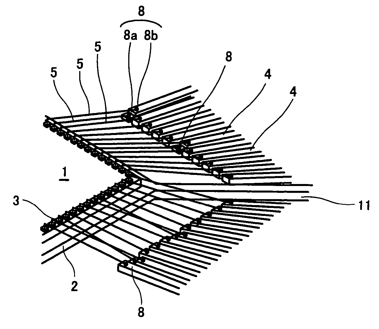
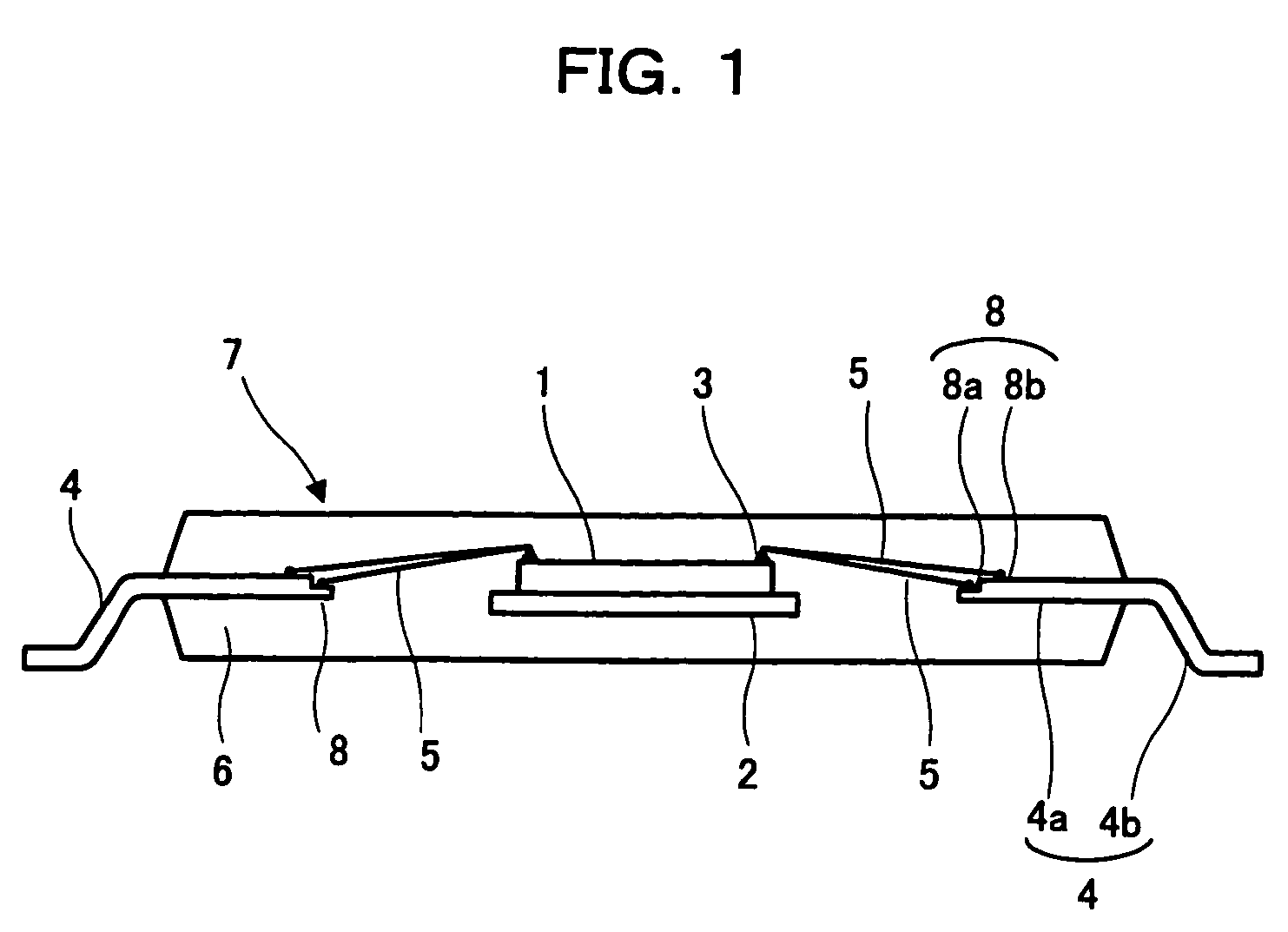
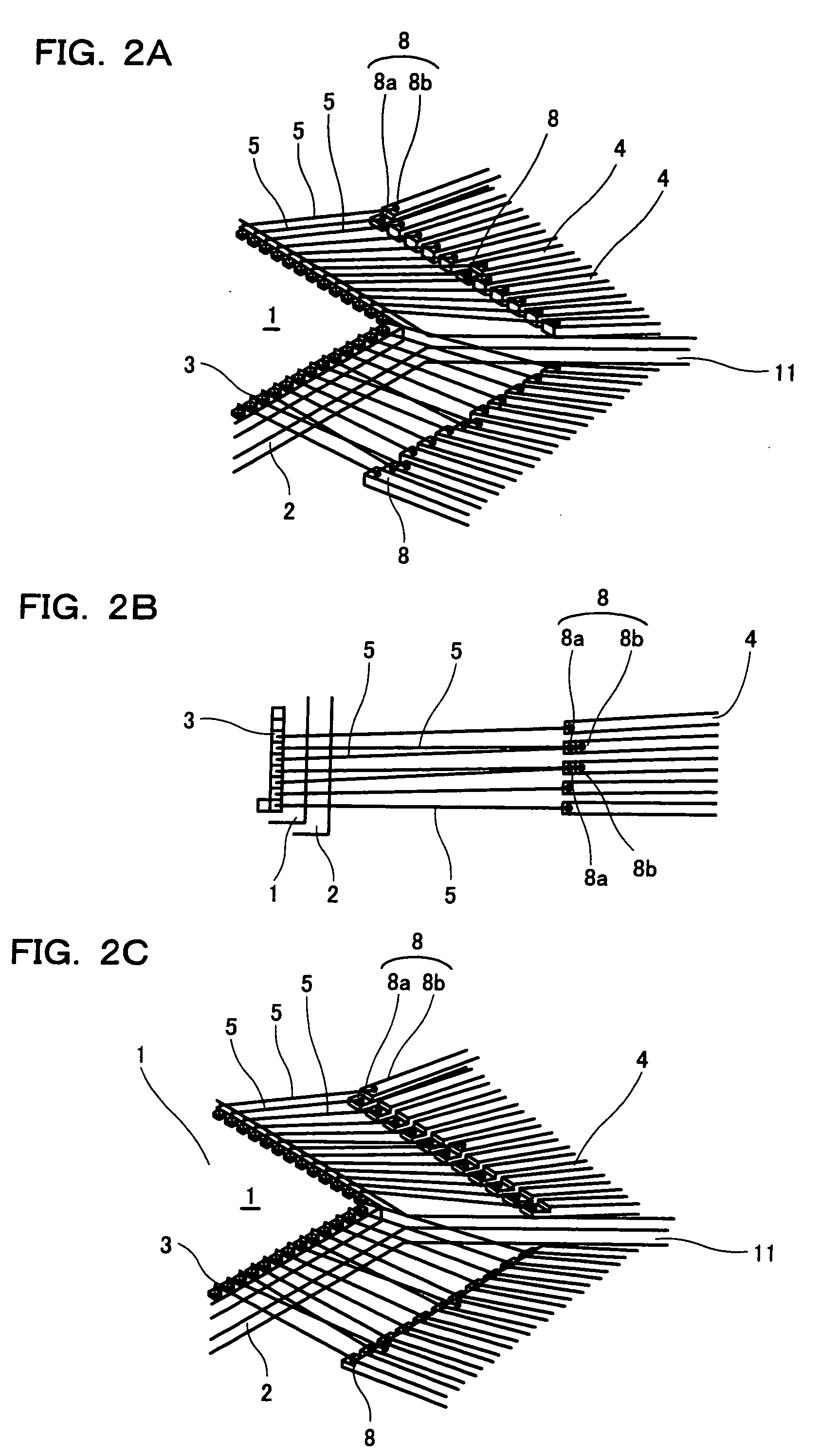
[0037]FIG. 1 is a cross sectional view of a semiconductor device according to a first embodiment of the invention, FIG. 2A is a view of an inner structure of a wire bonding section of the semiconductor device, and FIG. 2B is a view showing a frame format of the wire bonding section of the semiconductor device.
[0038] In the semiconductor shown in FIG. 1 and FIG. 2, the semiconductor chip 1 formed with an integrated circuit is mounted on the die pad 2, and the electrode 3 formed on the surface of the semiconductor chip 1 and the lead 4, which is radially arranged in the vicinity of the die pad 2, are connected with the wire 5. The semiconductor chip 1, the wire 5, and the inner lead 4a of the lead 4 are collectively resin molded with the sealing resin 6 to from the resin sealing body 7. The outer lead 4b continuing from the inner lead 4a is bent and molded into a gull-wing shape at the exterior of the resin sealing body 7.
[0039] This semiconductor device differs from the conventiona...
second embodiment
[0057]FIG. 5 is a cross sectional view of a main part showing the configuration of the wire bonding section of a semiconductor device according to a second embodiment of the invention.
[0058] The semiconductor device of the second embodiment differs from that of the first embodiment in that the step portion at the tip end corresponding to the wire bonding region 8a is formed by being bent using a press metal mold when forming the step part 8 of the inner lead 4a.
[0059] According to this method, the variation in the thickness and the width of the step portion at the tip end of the inner lead 4 is suppressed. In the method of the first embodiment, the step portion at the tip end corresponding to the wire bonding region 8a is made thin by etching or pressing from the wire bonding surface side, as mentioned above, and thus the front and the back of the step, that is, the boundary between the wire bonding region 8a at the front of the tip end of the inner lead 4a and the wire bonding re...
third embodiment
[0062]FIG. 6 is a cross sectional view of a main part showing a configuration of the wire bonding section of a semiconductor device according to a third embodiment of the invention.
[0063] The semiconductor device of the third embodiment differs from that of the first embodiment in that the step portion at the tip end corresponding to the wire bonding region 8a is formed by being pushed down in the vertical direction using a press metal mold when forming the step part 8 of the inner lead 4a.
[0064] According to this method, not only is the variation in the thickness and the width of the step portion at the tip end of the inner lead 4 suppressed, but compared to the second embodiment, the length of the second or the subsequent wire 5 can be made short. In the second embodiment, bending is simply performed using the press metal mold, and thus a region for bending in the direction of the lead length is required, that is, an inclined portion to where wire bonding cannot be performed is ...
PUM
 Abstract
Description
Claims
Application Information
 - R&D
- Intellectual Property
- Life Sciences
- Materials
- Tech Scout
- Unparalleled Data Quality
- Higher Quality Content
- 60% Fewer Hallucinations
Browse by: Latest US Patents, China's latest patents, Technical Efficacy Thesaurus, Application Domain, Technology Topic, Popular Technical Reports.
© 2025 PatSnap. All rights reserved.Legal|Privacy policy|Modern Slavery Act Transparency Statement|Sitemap|About US| Contact US: help@patsnap.com


