
Insulated wire

a technology of insulated wire and sn plate, which is applied in the direction of insulated conductors, cables, conductors, etc., can solve the problems of easy peeling, and low melting point of conventional technology, so as to reduce the deterioration of shock resistance and good abrasion resistance

Active Publication Date: 2018-03-01
AUTONETWORKS TECH LTD +2
View PDF2 Cites 0 Cited by
  • Summary
  • Abstract
  • Description
  • Claims
  • Application Information

AI Technical Summary

Benefits of technology

The present patent aims to provide an insulated wire that can effectively manage corrosion caused by high-temperature oil, maintaining its shock resistance and preventing cracks even when bent or exposed to bending. The wire includes a stranded wire conductor with a Ni-based plated layer that shows high melting point and resistance to peeling or decreasing in cross-sectional area due to corrosion. The insulator, made of a cross-linked ethylene-tetrafluoroethylene based copolymer, is highly strong and resistant to abrasion. Overall, the insulated wire can efficiently reduce the impact of corrosion and maintain its performance in high-temperature environments.

Problems solved by technology

However, the conventional technology is problematic in the following point.
However, the melting point of the Sn plate is relatively low.
Therefore, due to the heat during the heat treatment for softening copper, the Sn plated layer tends to melt and to easily peel.
Consequently, the conventional insulated wire is problematic in that due to corrosion of the copper element wires caused by the high-temperature oil, the conductor cross-sectional area of the stranded wire conductor decreases and the shock resistance deteriorates.
However, the strength of perfluoro resins is low because the cross-linkage is difficult.
Thus, the conventional insulated wire is problematic in that the abrasion resistance of the insulator tends to deteriorate if the thickness of the insulator is reduced.
However, the conventional insulated wire is problematic in that the insulator easily cracks in the case where the insulated wire is exposed to a high-temperature oil as described above with being bent, and is once released from bending, and is once again bent.

Method used


Image

  • Insulated wire
  • Insulated wire
  • Insulated wire

Examples


example 1

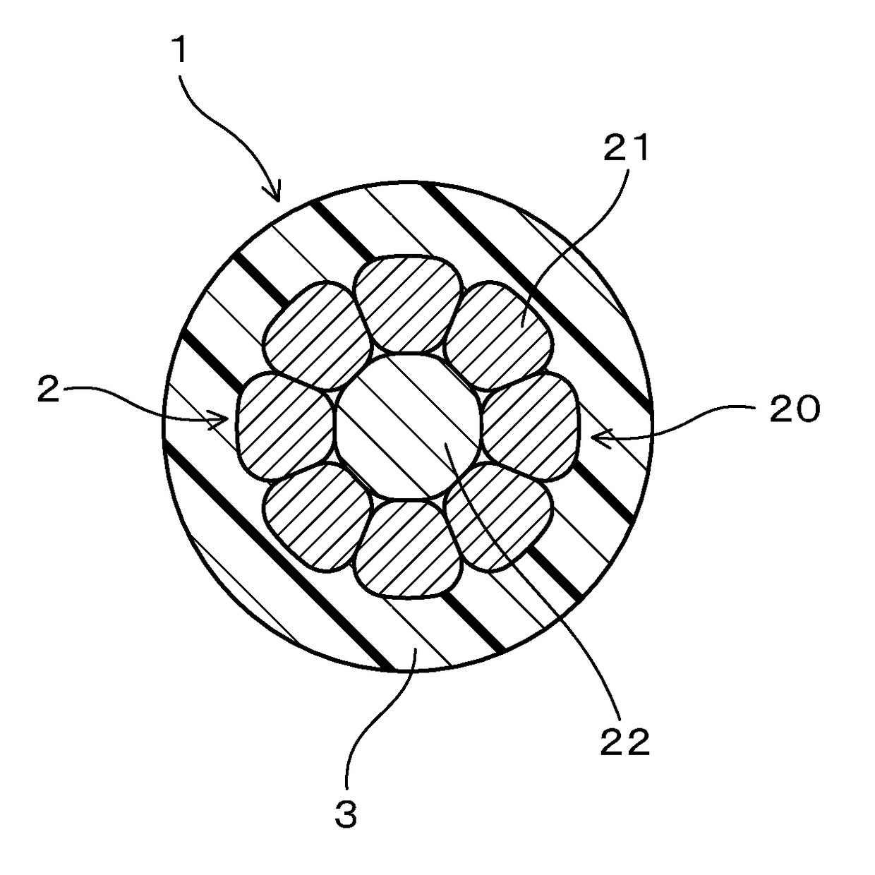
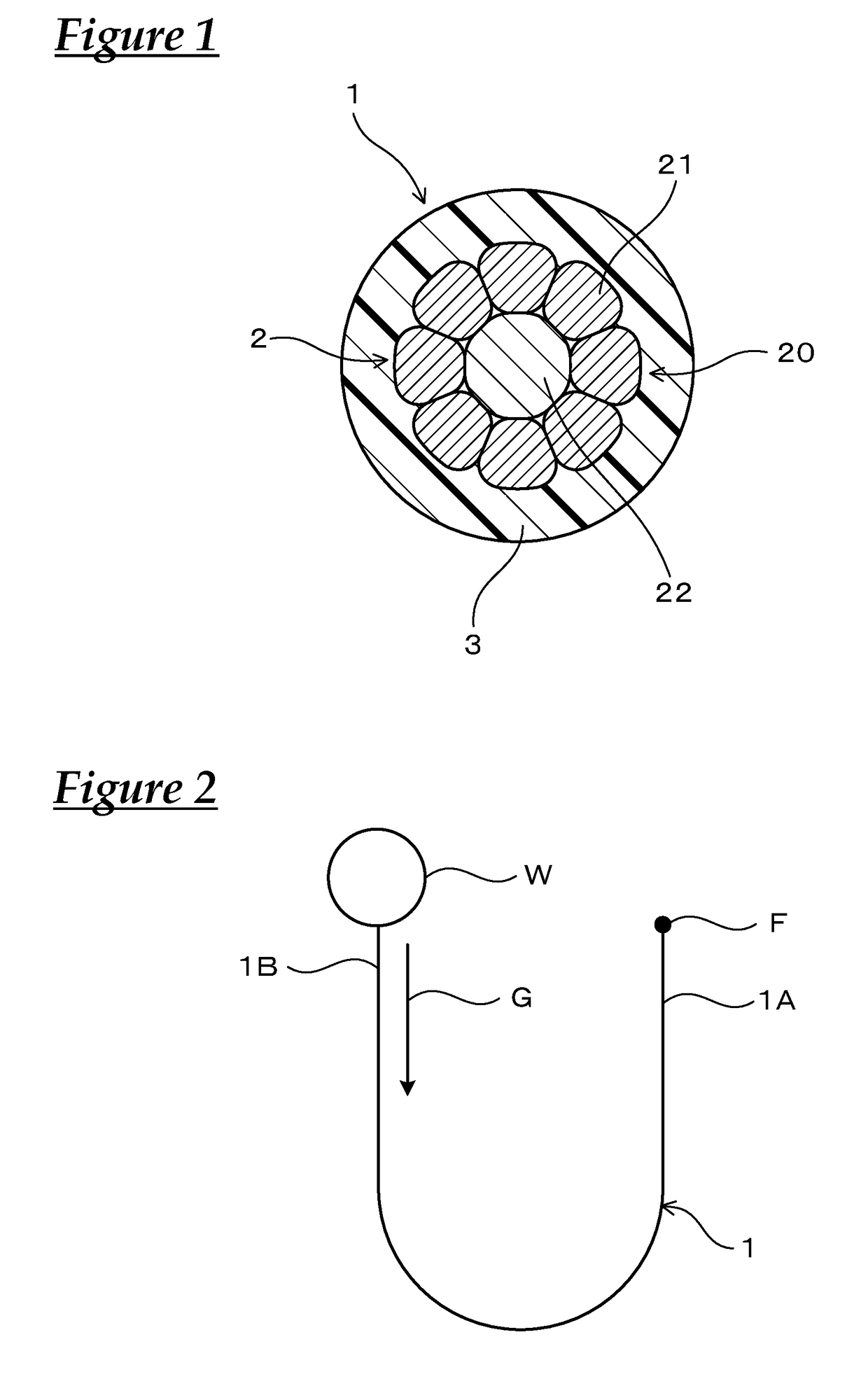
[0046]An insulated wire in Example 1 will be described with use of FIG. 1. As shown in FIG. 1, an insulated wire 1 in the example includes a stranded wire conductor 2 and an insulator 3 that covers the outer circumference of the stranded wire conductor 2. In the following, this will be described in detail.

[0047]The insulated wire 1 is configured to be used in a state of being in contact with an oil composed of AT fluid or CVT fluid. The stranded wire conductor 2 is made up of at least a plurality of copper-based element wires 21 that are twisted together, and has been heat-treated after circular compression. The copper-based element wires 21 have a Ni-based plated layer (not illustrated) on the surface, and the Ni-based plated layer has been compressed by the circular compression. The insulator 3 is composed of a cross-linked ethylene-tetrafluoroethylene based copolymer.

[0048]In the example, the base material of the copper-based element wires 21 is composed of copper or a copper all...

experimental example

[0060]As the material of the insulator, the following resins were prepared.[0061]ETFE (ethylene-tetrafluoroethylene copolymer) (“Fluon (Registered Trademark) ETFE C-55AP” manufactured by Asahi Glass Co., Ltd.)[0062]PTFE (tetrafluoroethylene resin) (“Fluon (Registered Trademark) PTFE CD097E” manufactured by Asahi Glass Co., Ltd.)[0063]PFA (tetrafluoroethylene-perfluoroalkyl vinyl ether copolymer) (“NEOFLON (Registered Trademark) PFA AP230” manufactured by Daikin Industries, Ltd.)[0064]FEP (tetrafluoroethylene-tetrafluoropropylene copolymer) (“NEOFLON (Registered Trademark) FEP AP230” manufactured by Daikin Industries, Ltd.)[0065]PP (polypropylene) (“NOVATEC PP EA9” manufactured by Japan Polypropylene Corporation)

[0066]As shown in Table 1, eight copper-based element wires each of which had a predetermined outer diameter and each of which had a Ni-base plated layer formed of a Ni plate on the surface were twisted together on the outer circumference of a stainless wire as a tension memb...


PUM

PropertyMeasurementUnit
thicknessaaaaaaaaaa
thicknessaaaaaaaaaa
thicknessaaaaaaaaaa

Abstract

An insulated wire that has a stranded wire conductor, and an insulator that covers an outer circumference of the stranded wire conductor. The stranded wire conductor is made up of at least a plurality of copper-based element wires twisted together, and has been heat-treated after circular compression. The copper-based element wire(s) has (have) an Ni-based plated layer on the surface. The Ni-based plated later has been compressed by the circular compression. The insulator is composed of a cross-linked ethylene-tetrafluoroethylene based copolymer, and has a heating deformation rate in the range of 65% or more, as determined under predetermined conditions using predetermined formulae in conformity with ISO6722.

Description

CROSS REFERENCE TO RELATED APPLICATIONS[0001]This application claims the priority of Japanese patent application JP2015-072900 filed on Mar. 31, 2015, the entire contents of which are incorporated herein.TECHNICAL FIELD[0002]The present invention relates to an insulated wire.BACKGROUND ART[0003]In the field of vehicles such as automobiles, there is conventionally known an insulated wire including a stranded wire conductor that is formed of a plurality of conductor element wires twisted together and an insulator that covers the outer circumference of the stranded wire conductor.[0004]As the stranded wire conductor, specifically, Patent Document 1 (JP-A-2008-159403) discloses a stranded wire conductor including a stainless element wire and a plurality of bare copper element wires that are twisted together on the outer circumference of the stainless element wire. Further, the document describes a technique for softening copper in which the bare copper element wires is subjected to heat...

Claims


Application Information

Patent Timeline
Patent Type & Authority Applications(United States)
IPC IPC(8): H01B7/18H01B1/02H01B13/00H01B3/44
CPCH01B7/1895H01B1/026H01B13/0016H01B3/445H01B7/02H01B5/104H01B7/0009H01B7/18H01B7/2806
Inventor FURUKAWA, TOYOKIOOI, HAYATOHAYAMI, HIROSHIHORI, KENJI
Owner AUTONETWORKS TECH LTD
Learn More