Eureka AIR delivers breakthrough ideas for toughest innovation challenges, trusted by R&D personnel around the world.

System and method for position correction using power line carrier communications

a technology of power line carrier and communication system, applied in the field of system and method of position correction using power line carrier communication, can solve the problems of system delay, poor reliability of wireless system, high cost, etc., and achieve the effect of improving communication and location awareness

Active Publication Date: 2020-12-08
VALMONT IND INC
View PDF12 Cites 1 Cited by
  • Summary
  • Abstract
  • Description
  • Claims
  • Application Information

AI Technical Summary

Benefits of technology

[0013]According to a further preferred embodiment, alignment may be maintained by calculating a straight, center line between the pivot and the last regular drive unit; calculating the relative distances between each intermediate drive tower and the calculated center line; and controlling the speed or average run time of each intermediate drive tower to reduce distance between their current locations and the calculated center line.

Problems solved by technology

Both of these solutions are costly and prone to communication errors.
Hard-wired systems require the installation of significant lengths cable and wireless systems often require repeater stations to boost the radio signals over long distances.
Further, wireless systems have poor reliability due to distance, weather changes, obstacles, induced RF noise and long latencies, particularly with cellular communications.
Both systems have caused errors in position reporting and have caused system delays due to failed communications.
The end result of these errors has been poor water application uniformity, delays in application and other problems which have reduced yields and profitability for growers.

Method used


Image

  • System and method for position correction using power line carrier communications
  • System and method for position correction using power line carrier communications
  • System and method for position correction using power line carrier communications

Examples


Embodiment Construction

[0025]For the purposes of promoting an understanding of the principles of the present invention, reference will now be made to the embodiments illustrated in the drawings and specific language will be used to describe the same. It will nevertheless be understood that no limitation of the scope of the present invention is hereby intended and such alterations and further modifications in the illustrated devices are contemplated as would normally occur to one skilled in the art.

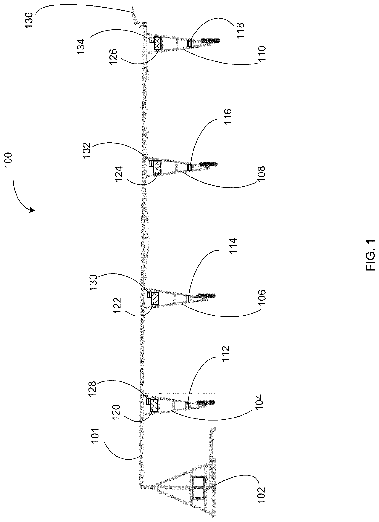
[0026]In accordance with preferred embodiments of the present invention, it should be understood that the term “drive unit” may preferably include a number of sub-components including: a motor, a controller, a communication device (such as a PLC or the like) and an alignment device. Further, while the invention is discussed below with respect to four exemplary towers, the number of towers used may be expanded or reduced (i.e. 1-100 towers) as needed without departing from the spirit of the present invention. Fur...


PUM


Abstract

The present invention provides a method for aligning spans using real-time kinetics (RTK) data communicated through a power line carrier system. According to a further preferred embodiment, the method of present invention includes the steps of: receiving a first set of GPS location data and second set of RTK data; comparing the first set of GPS location data with the second set of RTK data; calculating RTK error correction data; creating an RTK error correction data signal containing RTK error correction data; modulating the RTK error correction data signal for transmission on a power line carrier; transmitting the RTK error correction data signal through a power line BUS onto a power line to a last drive tower; de-modulating the RTK error correction data signal; calculating the location of the last drive tower using the RTK error correction data; calculating a straight, center line between the pivot and the last drive unit; calculating the relative distances between each intermediate drive tower and the calculated center line; and controlling the speed or average run time of each intermediate drive tower to reduce distance between their current locations and the calculated center line.

Description

RELATED APPLICATIONS[0001]The present application claims priority to U.S. Provisional Application No. 62 / 723,663 filed Aug. 28, 2018.BACKGROUND AND FIELD OF THE PRESENT INVENTIONField of the Present Invention[0002]The present invention relates generally to a system and method for providing correction and position signals to various powered elements within an irrigation machine to achieve a variety of objectives, including alignment control of irrigation spans, guidance of irrigation machines (e.g. corners and linears) and to provide positional information to a variety of remote monitoring and control devices.Background of the Invention[0003]Modern center pivot and linear irrigation systems generally include interconnected spans (e.g., irrigation spans) supported by one or more tower structures to support the conduits (e.g., water pipe sections). In turn, the conduits are further attached to sprinkler / nozzle systems which spray water (or other applicants) in a desired pattern. In the...

Claims


Application Information

Patent Timeline
Patent Type & Authority Patents(United States)
IPC IPC(8): H04B3/54G01S19/51A01G25/16H04L12/40B05B12/06A01G25/09B05B12/12G01S19/43
CPCH04B3/546A01G25/16B05B12/06G01S19/51A01G25/092H04L12/40045B05B12/124G01S19/43
Inventor MOELLER, MARKTHATCHER, TRACY A.
Owner VALMONT IND INC
Why Eureka
Eureka Blog
Learn More