
Polarization independent wideband reflectors and methods for their manufacture

a wideband reflector and polarization independent technology, applied in the direction of optics, instruments, diffraction gratings, etc., can solve the problems of limited wideband reflection in this one-dimensional (1d) grating architecture, impractical multi-layer deposition, etc., and achieve wide spectral reflection bands, simple design, and robust performance.

Active Publication Date: 2020-12-29
MAGNUSSON ROBERT +3
View PDF2 Cites 0 Cited by
  • Summary
  • Abstract
  • Description
  • Claims
  • Application Information

AI Technical Summary

Benefits of technology

This approach results in a robust, high-efficiency unpolarized reflection band with reflectance exceeding 99.9% across a wide spectral range, improving upon individual polarization-sensitive reflectors by enhancing reflectance values and tolerating parametric deviations and incidence angle variations.

Problems solved by technology

Moreover, at longer wavelengths of light, in mid-infrared and THz domains for instance, multiple layer deposition becomes impractical on account of typically-slow deposition techniques and issues in maintaining consistent deposition conditions across long time spans.
Practical challenges in fabrication include the need for periodic patterning, precision control of etching processes to maintain grating features, and management of process-induced scattering centers.
Thus, wideband reflection in this one-dimensional (1D) grating architecture is limited to a single polarization.

Method used


Image

  • Polarization independent wideband reflectors and methods for their manufacture
  • Polarization independent wideband reflectors and methods for their manufacture
  • Polarization independent wideband reflectors and methods for their manufacture

Examples


example 1

Sequentially Arranged Wideband Reflector Concept

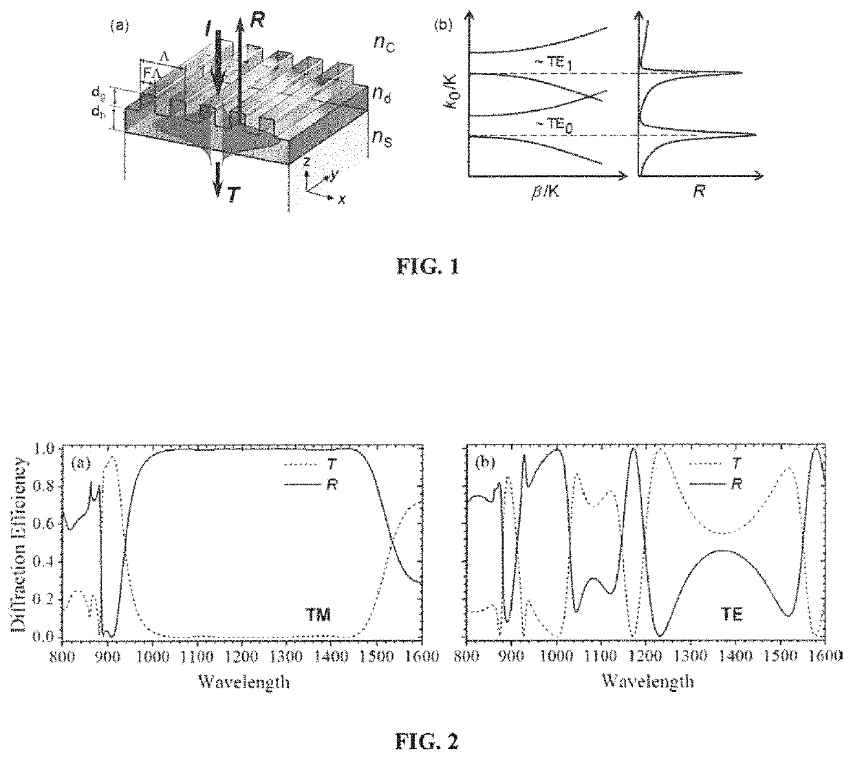
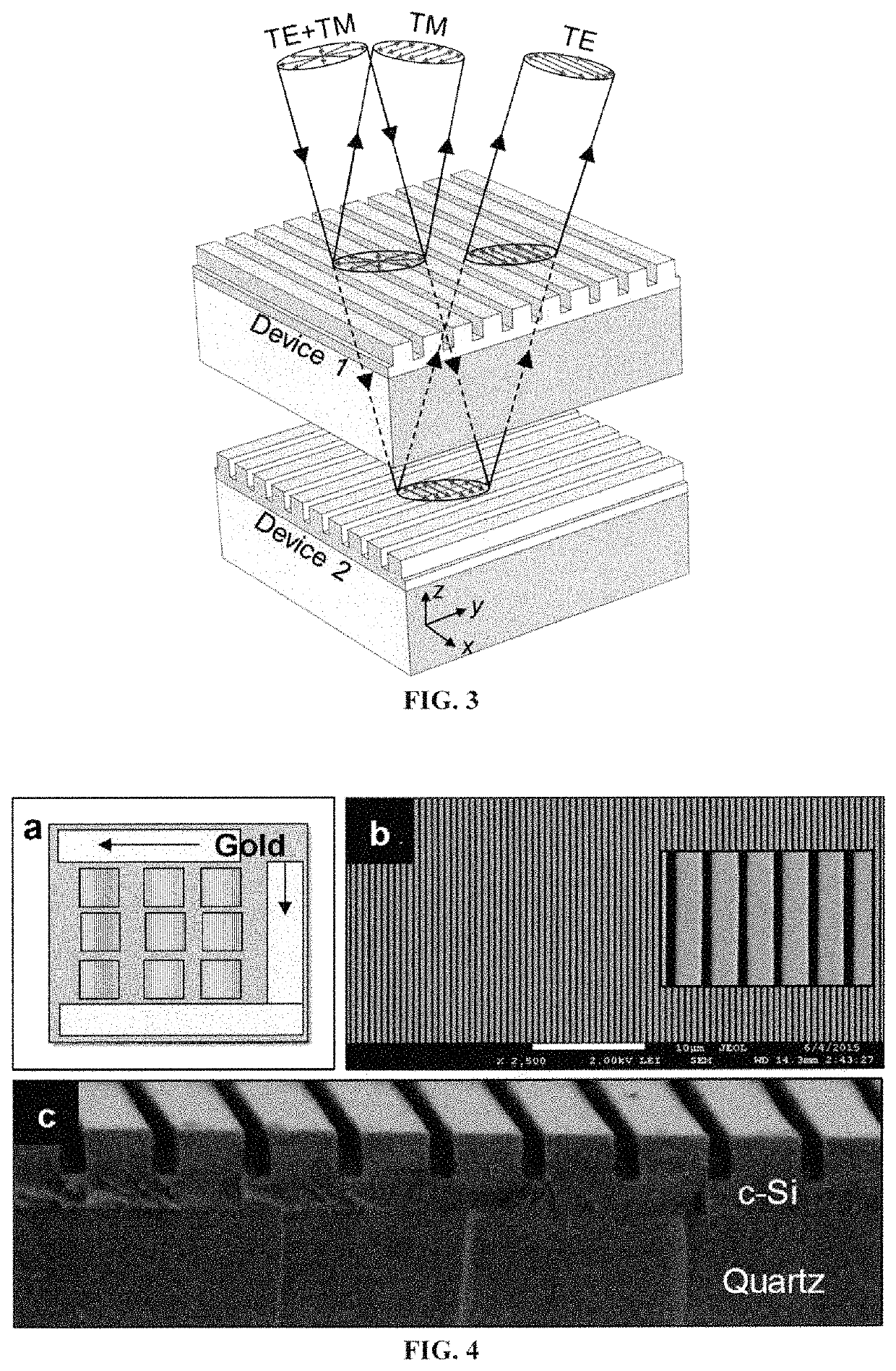
[0038]FIG. 3 illustrates a sequentially arranged wideband reflector schematic. Device 1 and Device 2 are polarization-sensitive wideband reflectors made with zero-contrast gratings (ZCGs) working in TM polarization. When the devices are sequentially arranged such that their grating planes are parallel (x-y plane) and their grating vectors K are orthogonal to one another, wherein K is along the y-axis for Device 1 and the x-axis for Device 2, the overall sequential-arrangement becomes polarization insensitive. For unpolarized input light with TE+TM components, Device 1 near-completely reflects the TM components and partially transmits the TE components. This transmitted TE component is TM polarized with respect to Device 2 and is also completely reflected. This results in near-complete reflection of both TE and TM components resulting in polarization-insensitive wideband reflection. Note that because Device 1 and Device 2 also partially...

example 2

Experimental Demonstration of Unpolarized Wideband Reflectors With Sequential ZCGs

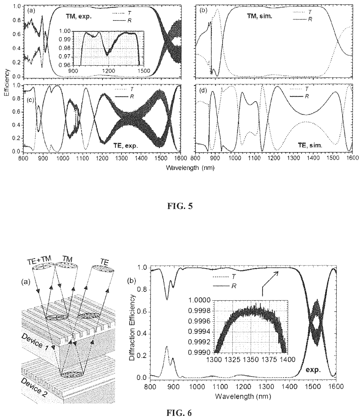
[0039]FIG. 4 depicts SEMs pertinent to a fabricated 1D ZCG broadband mirror. FIG. 4(a) shows a photograph of an array of nine fabricated devices on a 1×1 inch2 SOQ wafer. Each device is 5×5 mm2. Approximately 100-nm-thick gold film is sputtered on the non-device edges of the SOQ wafer. Scanning-electron micrographs showing FIG. 4(b) top-view and FIG. 4(c) cross-sectional images of a representative device. FIG. 5 presents the polarization-dependent spectral response of one of the devices in the array. In particular, FIG. 5(a) shows experimental and FIG. 5(b) simulated zero-order T and R spectra for TM polarized light incidence. FIG. 5(c) furnishes experimental and FIG. 5(d) simulated T and R spectra for TE polarized light incidence. Device parameters are fill factor F=0.63, grating depth dg=330 nm, c-Si film thickness t=520 nm, and grating period Λ=560 nm in both experiment and simulation. Inset in FIG....

example 3

Experimental Reflector Fabricated in Amorphous Silicon-On-Glass

[0040]In a second experimental example, we implement the sequential ZCG arrangement shown in FIG. 3 with a pair of wideband reflectors fabricated in a silicon-on-glass platform as opposed to the previous SOQ example. The two polarization-sensitive reflectors share similar experimental grating parameters that are Λ=856 nm, F=0.54, dg=563 nm, and dh=408 nm. FIG. 8(a) shows an AFM of a representative fabricated device and FIG. 8(b) shows an SEM of a 2×2 array of devices that each measure 5×5 mm2. The reflectors are made with a-Si sputtered onto a substrate of soda-lime glass. FIG. 9(a) reveals the spectral properties of a single prototype a-Si ZCG reflector depicting both numerical and experimental data. There results a wide high-efficiency band for TM polarization extending from λ˜1.7 μm to λ˜2.3 μm. FIG. 9(b) schematically shows the response of the serial reflectors to the two polarization components present in the input ...


PUM

PropertyMeasurementUnit
air gap distanceaaaaaaaaaa
thickaaaaaaaaaa
Rayleigh wavelengthaaaaaaaaaa

Abstract

Unpolarized broadband reflectors enabled by a serial arrangement of a pair of polarized subwavelength gratings are disclosed. Device illustrations include partially-etched crystalline-silicon films on quartz substrates and amorphous silicon films on glass. The individual reflectors exhibit extremely wide spectral reflection bands in one polarization. By arranging two such reflectors sequentially with orthogonal periodicities, there results an unpolarized spectral band that exceeds those of the individual polarized bands. In the prototypes disclosed, there results zero-order reflectance exceeding 97% under unpolarized light incidence over a 500-nm-wide wavelength band. This wideband represents a ˜44% fractional band in the near infrared spectral band. The elemental polarization-sensitive reflectors based on one-dimensional resonant gratings have simple design, robust performance, and are straightforward to fabricate. Hence, this technology is a promising alternative to traditional multilayer thin-film reflectors especially at longer wavelengths of light where multilayer deposition may be infeasible or impractical.

Description

CROSS REFERENCE TO RELATED APPLICATION[0001]This application claims priority pursuant to 35 U.S.C. § 119(e) to U.S. Provisional Patent Application Ser. No. 62 / 222,070, filed on Sep. 22, 2015, which is hereby incorporated by reference in its entirety.STATEMENT REGARDING FEDERALLY SPONSORED RESEARCH[0002]This invention was created with government support under grant number PF-AIR 1444922 awarded by the National Science Foundation. The government therefore has certain rights in the invention.FIELD[0003]This invention relates to a facile method to fabricate wideband unpolarized reflectors spectral ranges extending from the visible region to the millimeter or microwave regions. By arranging two or more one-dimensional grating-type resonant reflectors sequentially with orthogonal periodicities, there results an unpolarized spectral band that exceeds those of the individual polarized bands.BACKGROUND OF THE INVENTION[0004]Resonant broadband reflection arising from optical devices fashioned...

Claims


Application Information

Patent Timeline
Patent Type & Authority Patents(United States)
IPC IPC(8): G02B5/18G02B27/42
CPCG02B27/4277G02B27/4288G02B5/1861G02B5/1809
Inventor MAGNUSSON, ROBERTNIRAULA, MANOJKO, YEONG HWANLEE, KYU JIN
Owner MAGNUSSON ROBERT
Learn More