
Current sensor system

a current sensor and sensor technology, applied in the direction of instruments, magnetic measurements, measurement devices, etc., can solve the problems of impracticality or inability to illustrate and describ

Active Publication Date: 2021-01-05
ALLEGRO MICROSYSTEMS INC
View PDF31 Cites 3 Cited by
  • Summary
  • Abstract
  • Description
  • Claims
  • Application Information

AI Technical Summary

Benefits of technology

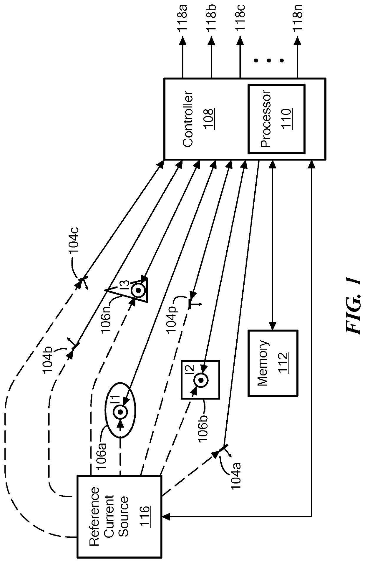
The present patent provides a magnetic field sensor for measuring current that allows for improved accuracy and reduced impact from stray fields. The sensor system includes multiple current sensors and conductors carrying the current to be measured. Each current sensor has a magnetic field sensing element that generates a magnetic field signal to indicate the detected magnetic field. The technical effect is an improved accuracy and reliability of current measurement systems.

Problems solved by technology

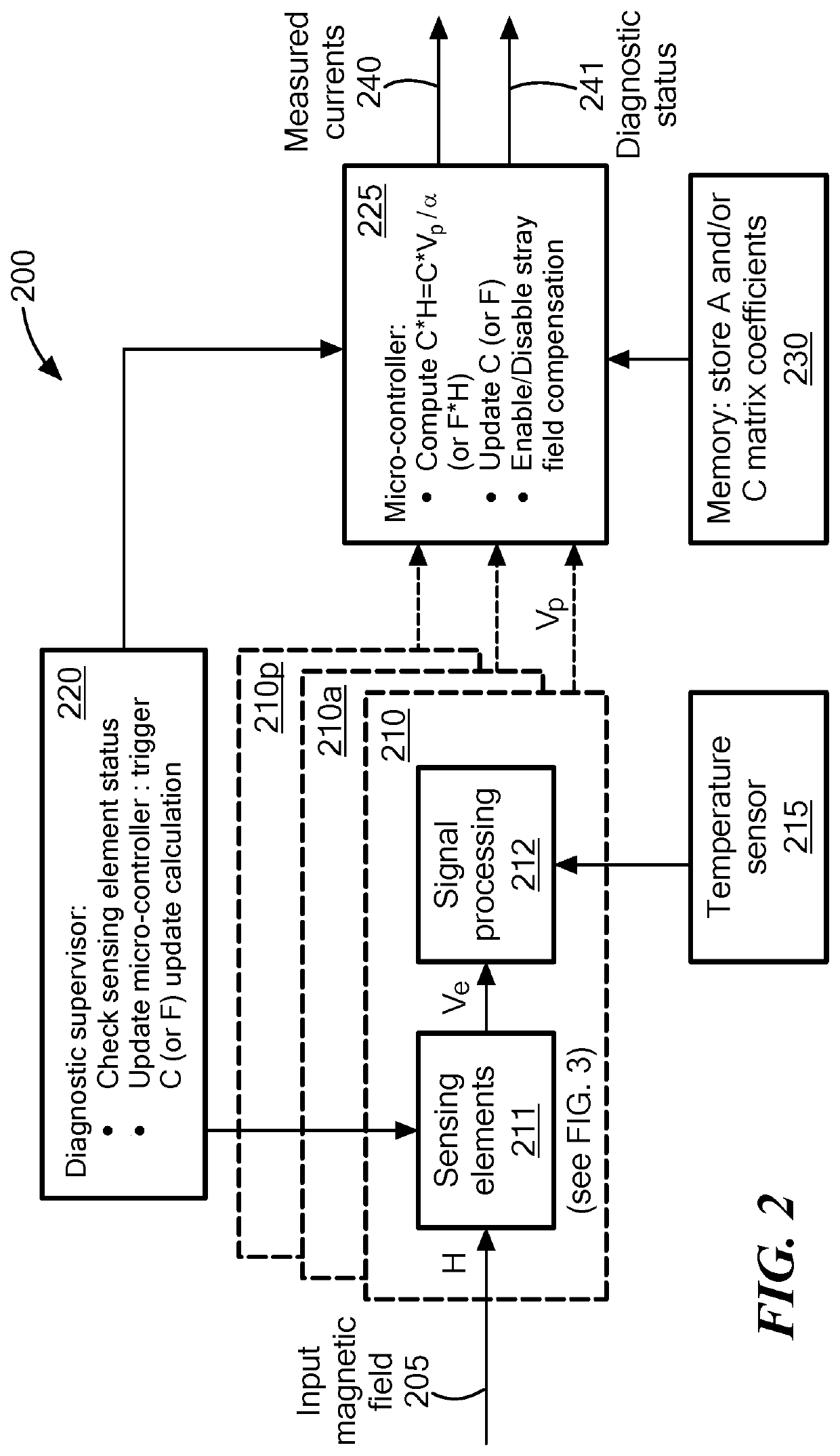
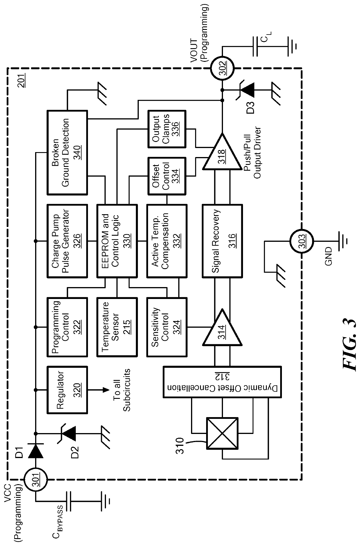
Since it is often impractical or impossible to illustrate and describe every possible embodiment, the provided figures depict one or more exemplary embodiments.

Method used


Image

  • Current sensor system
  • Current sensor system
  • Current sensor system

Examples


Embodiment Construction

[0027]Before describing the present invention, some introductory concepts and terminology are explained.

[0028]As used herein, the term “magnetic field sensing element” is used to describe a variety of electronic elements that can sense a magnetic field and generate a magnetic field signal responsive to the magnetic field sensing element. The magnetic field sensing element can be, but is not limited to, a Hall-effect element, a fluxgate, a magnetoresistance element, or a magnetotransistor. As is known, there are different types of Hall-effect elements, for example, a planar Hall element, a vertical Hall element, and a Circular Vertical Hall (CVH) element. As is also known, there are different types of magnetoresistance elements, for example, a semiconductor magnetoresistance element such as an Indium Antimonide (InSb) element, a giant magnetoresistance (GMR) element, for example, a spin valve, an anisotropic magnetoresistance element (AMR), a tunneling magnetoresistance (TMR) element...


PUM


Abstract

Apparatus and methods provide a current sensor system including a plurality of current sensors positioned proximate a plurality of conductors. Each conductor is configured to carry a current to be measured. Each current sensor comprises one or more magnetic field sensing elements configured to generate a respective magnetic field signal indicative of a detected magnetic field. The plurality of current sensors includes a first number of current sensors and the plurality of conductors includes a second number of conductors such that the first number is at least one more than the second number. A controller is coupled to receive the magnetic field signal from each of the current sensors and, for each magnetic field sensing element, is configured to characterize a magnetic coupling between the magnetic field sensing element and each of the plurality of conductors.

Description

CROSS REFERENCE TO RELATED APPLICATIONS[0001]Not Applicable.STATEMENT REGARDING FEDERALLY SPONSORED RESEARCH[0002]Not Applicable.FIELD[0003]The present disclosure relates generally to methods for determining current in a conductor using magnetic field sensors.BACKGROUND[0004]Some conventional electrical current sensors are positioned near a current-carrying conductor to sense a magnetic field generated by the current through the conductor. The current sensor generates an output signal having a magnitude proportional to the magnetic field induced by the current through the conductor.[0005]The accuracy with which a magnetic field-based current sensor senses an intended current can be affected by its immunity to stray magnetic fields. Some conventional current sensors employ a ferromagnetic core to increase the coupling between the current flowing in the conductor and the magnetic field magnitude. The core may provide a shielding to stray field immunity or, if no ferromagnetic core is ...

Claims


Application Information

Patent Timeline
Patent Type & Authority Patents(United States)
IPC IPC(8): G01R15/20G01R19/00G01R33/025
CPCG01R15/205G01R15/202G01R33/025G01R33/072G01R33/091
Inventor VUILLERMET, YANNICKFRIEDRICH, ANDREAS P.
Owner ALLEGRO MICROSYSTEMS INC
Learn More