Wearable sensor and method for manufacturing same

a technology of wearable sensors and sensors, applied in the field of wearable sensors, can solve the problems of inconvenient wearing, limited sensitivity of wearable sensors for effective sensing biotransformation, and inconvenient wearing, so as to reduce the processing time for forming the carbon nanotube layer, improve the sensitivity and durability of wearable sensors, and prevent the exfoliation of carbon nanotube layers

Active Publication Date: 2021-01-12
MCELL CO LTD
View PDF6 Cites 4 Cited by
  • Summary
  • Abstract
  • Description
  • Claims
  • Application Information

AI Technical Summary

Benefits of technology

[0021]The wearable sensor according to an embodiment of the present invention provides carbon nanotubes (CNT) on a fiber to form a carbon nanotube layer, and the resistance displacement of the carbon nanotube layer according to the deformation of the fiber may be sensed or measured. Accordingly, the deformation of the fiber may be sensed by the resistance displacement of the carbon nanotube layer, the biotransformation of a wearer may be sensed by measuring the resistance displacement due to the deformation of the fiber, which may be displaced according to the biotransformation of the wearer.
[0022]In addition, in the present invention, a self-assembled monolayer including a functional group is formed on a fiber, a hydroxyl group (—OH) is formed on the surface of carbon nanotube, and a carbon nanotube layer is formed on the self-assembled monolayer formed in the fiber, and the bonding force between the fiber and the carbon nanotube layer may be increased due to the ionic bond of the functional group and the hydroxyl group, and thus, the sensitivity and durability of the wearable sensor may be improved. In addition, a ductile protective layer is coated on the carbon nanotube layer to prevent the exfoliation of the carbon nanotube layer.
[0023]Meanwhile, in the method for manufacturing a wearable sensor of the present invention, a carbon nanotube layer is formed by vacuum adsorption, and the carbon nanotube layer is adsorbed well on the fiber and a processing time for forming the carbon nanotube layer may be decreased. In addition, since the carbon nanotube layer is formed by an in-line process while transporting the fiber, the mass production of the wearable sensor may be further improved.

Problems solved by technology

Accordingly, the securing of the sensitivity of a sensor for effectively sensing the biotransformation is limited.
In addition, the conventional wearable devices are worn around the body apart from clothes, and wearing is inconvenient and a user may feel a pressure around a wearing part during wearing.
However, a fibrous apparatus (or sensor) which is a true wearable apparatus is not supplied so far.

Method used


Image

  • Wearable sensor and method for manufacturing same
  • Wearable sensor and method for manufacturing same
  • Wearable sensor and method for manufacturing same

Examples


Embodiment Construction

[0030]Hereinafter, embodiments of the present invention will be described in detail with reference to the accompanying drawings. The present invention may, however, be embodied in different forms and should not be construed as limited to the embodiments set forth herein. Rather, these embodiments are provided so that this disclosure will be thorough and complete, and will fully convey the scope of the present invention to those skilled in the art. In the explanation, the same element is imparted with the same reference numeral, and the dimensions of elements may be partially exaggerated for clarity of illustration. Like reference numerals refer to like elements throughout.

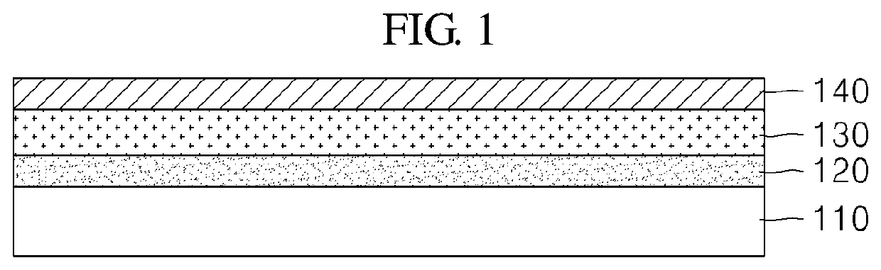
[0031]FIG. 1 is a schematic cross-sectional view showing a wearable sensor according to an embodiment of the present invention.

[0032]Referring to FIG. 1, the wearable sensor according to an embodiment of the present invention may include a fiber (110); a self-assembled monolayer (120) which is formed on at least on...


PUM

PropertyMeasurementUnit
temperatureaaaaaaaaaa
ductileaaaaaaaaaa

Abstract

The present invention provides a wearable sensor including a fiber; a self-assembled monolayer formed on at least one surface of the fiber and including a functional group; a carbon nanotube layer formed on the self-assembled monolayer by adsorbing a plurality of carbon nanotubes on the self-assembled monolayer; and an electrode electrically connected to the carbon nanotube layer.

Description

TECHNICAL FIELD[0001]The present invention relates to a wearable sensor and a method for manufacturing same, and more particularly, to a wearable sensor that senses the resistance displacement of a carbon nanotube layer according to the deformation of a fiber, and a method for manufacturing same.BACKGROUND ART[0002]Recently, due to the development in medical technology, desires on the promotion of health increase and concerns about information and communication technologies (ICT) increase, and thus, various wearable health care apparatuses and systems using the internet of things are appearing.[0003]The conventional wearable devices are mere smart devices which could be worn on the specific parts of the body such as a watch and a wristlet. Accordingly, the securing of the sensitivity of a sensor for effectively sensing the biotransformation is limited. In addition, the conventional wearable devices are worn around the body apart from clothes, and wearing is inconvenient and a user m...

Claims


Application Information

Patent Timeline
Patent Type & Authority Patents(United States)
IPC IPC(8): A61B5/11G01N27/12G01N33/36A61B5/00G01N33/497A61B5/113A61B5/04
CPCG01N27/12A61B5/11A61B5/6804G01N27/127G01N33/36A61B5/04A61B5/113A61B2562/0285A61B2562/12G01N33/497
Inventor JEE, SEUNG HYUNKIM, SUN HEE
Owner MCELL CO LTD
Why Eureka
Try Eureka