Cranioplasty plate assembly with pivotal struts

a technology of cranial artery and cranial artery, which is applied in the field of cranial artery assembly with pivotal artery, can solve the problems of increased patient risk, increased cost of cranioplasty surgery, and increased risk of patients during cranioplasty procedur

Active Publication Date: 2021-01-19
KARL LEIBINGER MEDIZINTECHNIK GMBH & CO KG +1
View PDF16 Cites 1 Cited by
  • Summary
  • Abstract
  • Description
  • Claims
  • Application Information

AI Technical Summary

Benefits of technology

[0020]The cranioplasty plate assembly, eliminates the need for cranioplasty surgery after brain swelling has receded. After the brain swelling completely resides, the plate can be lowered to a position adjacent or flush with the skull, without the need to replace the native bone.
[0021]In a preferred embodiment, the cranioplasty plate of the present invention is fixed to the skull at three equal-distant points. This preferred cranial plate has a rigid central portion and three rigid mounting tabs for attachment to the skull. Between the mounting tabs, at the perimeter of the plate, are malleable petals or tabs which are initially bent or angled downwardly toward the skull when a plate is in an initial raised position, and then extended substantially flat so as to be flush with the skull surface when the plate is in the lowered position, so as to provide a smooth interface between the plate and the skull surface.

Problems solved by technology

Without the skull protection, the brain is vulnerable under the skin until swelling reduces in the following weeks or months, until the cranioplasty surgery takes place to repair the skull defect.
The cranioplasty surgery increases the high costs associated with patient care.
The cranioplasty procedure also increases the patient risk, with potential brain injury from the significant manipulation of the brain which can cause intracranial hemorrhage and seizures, increased risk of infection, and wound breakdown.
Also, prior to the cranioplasty, patients often develop headaches and have delays in their recovery due to the loss of normal intracranial pressure gradient provided by the skull.

Method used


Image

  • Cranioplasty plate assembly with pivotal struts
  • Cranioplasty plate assembly with pivotal struts
  • Cranioplasty plate assembly with pivotal struts

Examples


Embodiment Construction

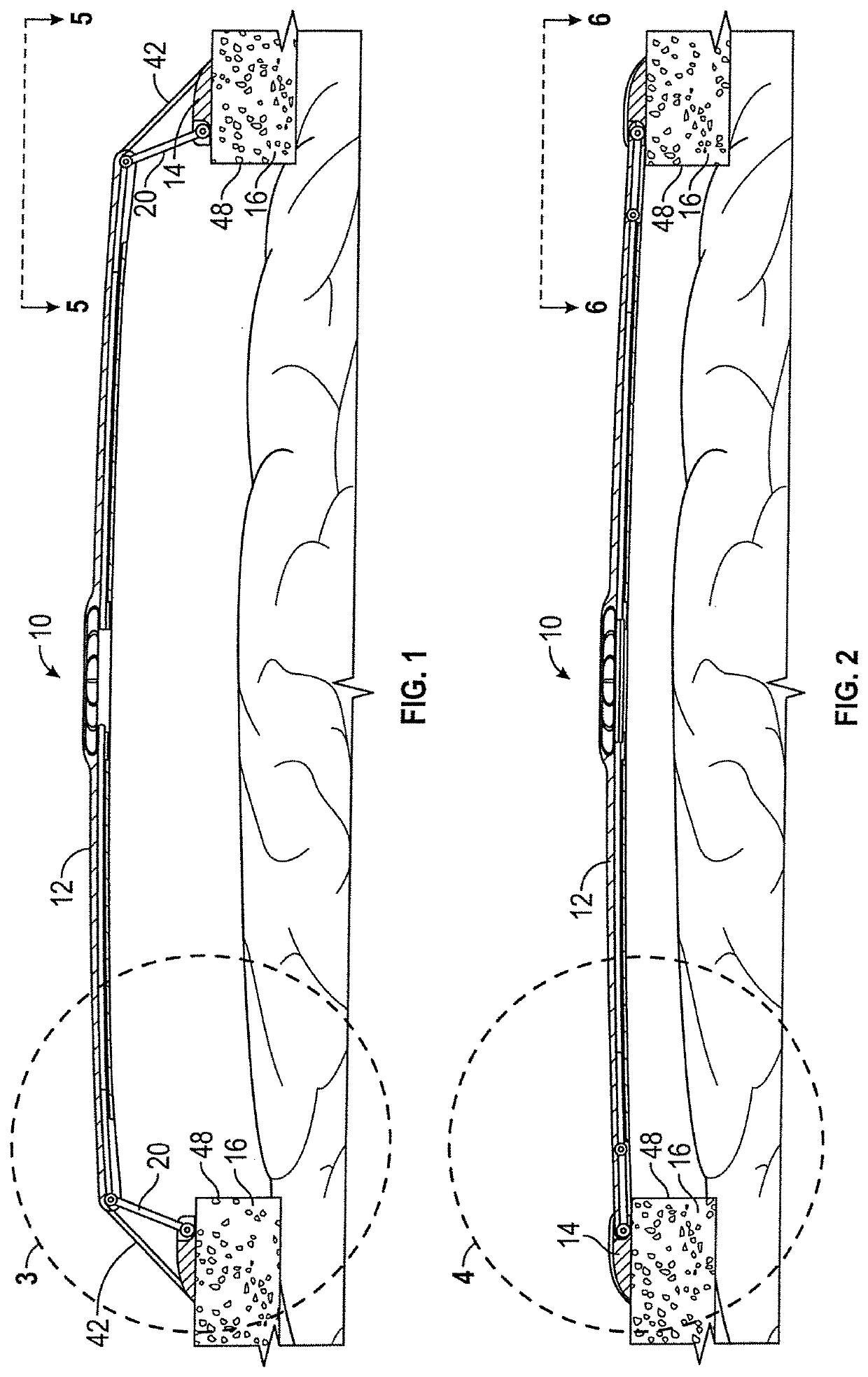
[0050]The present invention is directed towards a cranial plate assembly and method of surgically installing the assembly during a craniectomy neurosurgical procedure. The plate assembly is intended to replace the skull bone removed during the craniectomy, and eliminates the need for a follow up cranioplasty surgery, to replace the native bone.

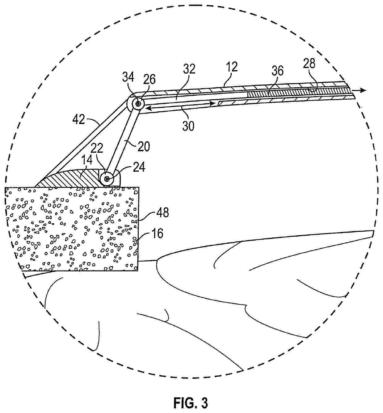
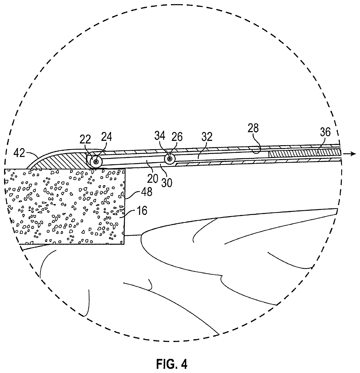
[0051]The cranial plate assembly of the present invention is generally designated by the reference numeral 10 in the drawings. The assembly 10 includes a plate 12 and a ring 14. The ring 14 is secured to a patient's skull 16 using screws 18. The plate 12 is attached to the ring 14 with struts 20 spaced equally around the plate 12. While, the drawings show the use of twelve struts 20 spaced 30° apart, it is understood that more or less struts can be utilized, with a minimum of three struts spaced 120° apart.

[0052]Each strut 20 has an outer end 20 pivotally connected to the ring 14 by a pin 24. Alternatively, the outer end 22 of each strut 20 ca...


PUM


Abstract

An adjustable cranioplasty plate assembly is provided for use following a craniectomy. The assembly includes a ring which is attached to the skull around the skull opening and a plate adjustably mounted to the ring. The plate is moveable between a raised position spaced above the ring and a lower position substantially flush with the ring. The plurality of extendable and retractable struts extends between the ring and the plate to provide the plate adjustability. The plurality of stay cables extending between the ring and the plate provide lateral stability in the raised position. The assembly replaces the native bone and eliminates the need for subsequent cranioplasty surgery. In one embodiment, the plate includes a rigid central portion, three rigid mounting tabs, and a plurality of malleable tapered perimeter petals which provide a smooth interface between the plate and the skull of the patient.

Description

CROSS-REFERENCE TO RELATED APPLICATIONS[0001]This claims priority to Provisional Application U.S. Ser. No. 62 / 338,120, filed on May 18, 2016, which is herein incorporated by reference in its entirety.BACKGROUND OF THE INVENTION[0002]A craniectomy is a medical surgical procedure commonly performed to manage intractable brain swelling, often caused by trauma or stroke. When a patient is managed using a standard craniectomy procedure, two surgeries are required. First, a craniectomy is performed, wherein a section of the skull is removed and then the skin or scalp is closed over the skull opening. The craniectomy allows for the brain tissue to expand through the opening to reduce intracranial pressure. After the brain swelling has receded, which may take several weeks or months, a second cranioplasty operation is required to replace the saved native bone material, or alternatively, to implant a prosthetic skull piece, such as a thin titanium skull plate. This second operation restores ...

Claims


Application Information

Patent Timeline
Patent Type & Authority Patents(United States)
IPC IPC(8): A61F2/28A61B17/80A61B17/68A61F2/30A61F2/48
CPCA61B17/8061A61B17/688A61F2/2875A61F2002/3052A61F2002/30462A61F2002/30471A61F2002/30537A61F2002/30578A61F2002/482A61B17/8085A61B17/8023A61B17/66A61F2/482
Inventor HOWARD, MATTHEW A.WAIZENEGGER, AXEL
Owner KARL LEIBINGER MEDIZINTECHNIK GMBH & CO KG
Why Eureka
Try Eureka