
Device and method with clock frequency supply

a clock frequency and device technology, applied in the direction of digital transmission, near-field rfid, near-field for read/write/interrogation/identification system, etc., can solve the problem of consuming a majority of power used, and achieve the effect of reducing the frequency differen

Active Publication Date: 2021-01-26
SAMSUNG ELECTRONICS CO LTD
View PDF20 Cites 1 Cited by
  • Summary
  • Abstract
  • Description
  • Claims
  • Application Information

AI Technical Summary

Benefits of technology

The patent text is talking about a device that can adjust the frequency of oscillation to make sure it matches the carrier frequency as closely as possible. This allows for better tuning and performance.

Problems solved by technology

In low-power wireless communications, a frequency synthesizer (for example, a phase locked loop (PLL) or a voltage-controlled oscillator (VCO)) may consume a majority of power used by a wireless transmission chip.

Method used


Image

  • Device and method with clock frequency supply
  • Device and method with clock frequency supply
  • Device and method with clock frequency supply

Examples


Embodiment Construction

[0043]Hereinafter, some examples will be described in detail with reference to the accompanying drawings. However, the scope of the present disclosure is not limited by the examples. Like reference numerals in the drawings denote like elements.

[0044]The following detailed description is provided to assist the reader in gaining a comprehensive understanding of the methods, apparatuses, and / or systems described herein.

[0045]However, various changes, modifications, and equivalents of the methods, apparatuses, and / or systems described herein will be apparent after an understanding of the disclosure of this application. For example, the sequences of operations described herein are merely examples, and are not limited to those set forth herein, but may be changed as will be apparent after an understanding of the disclosure of this application, with the exception of operations necessarily occurring in a certain order. Also, descriptions of features that are known in the art may be omitted ...


PUM


Abstract

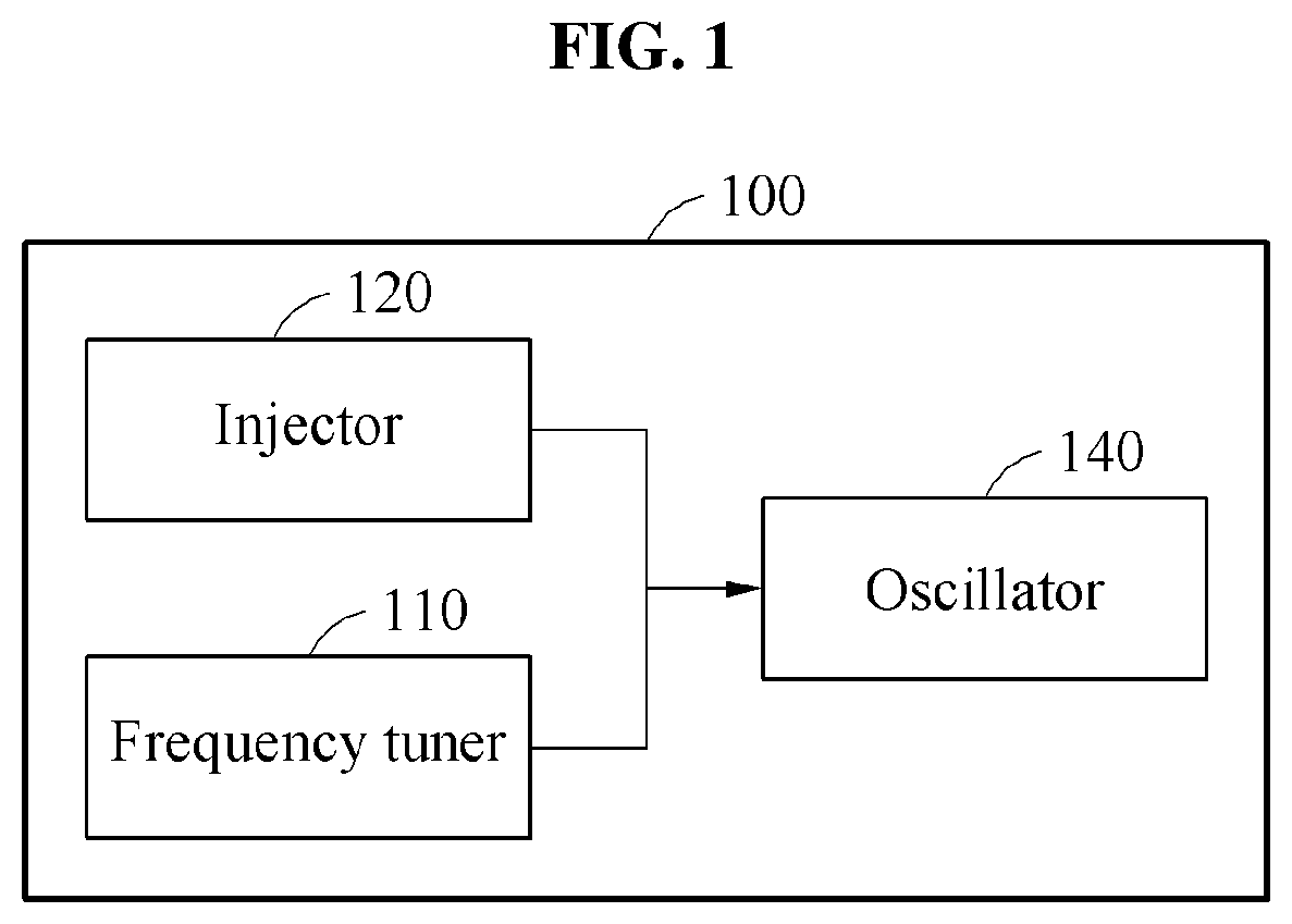
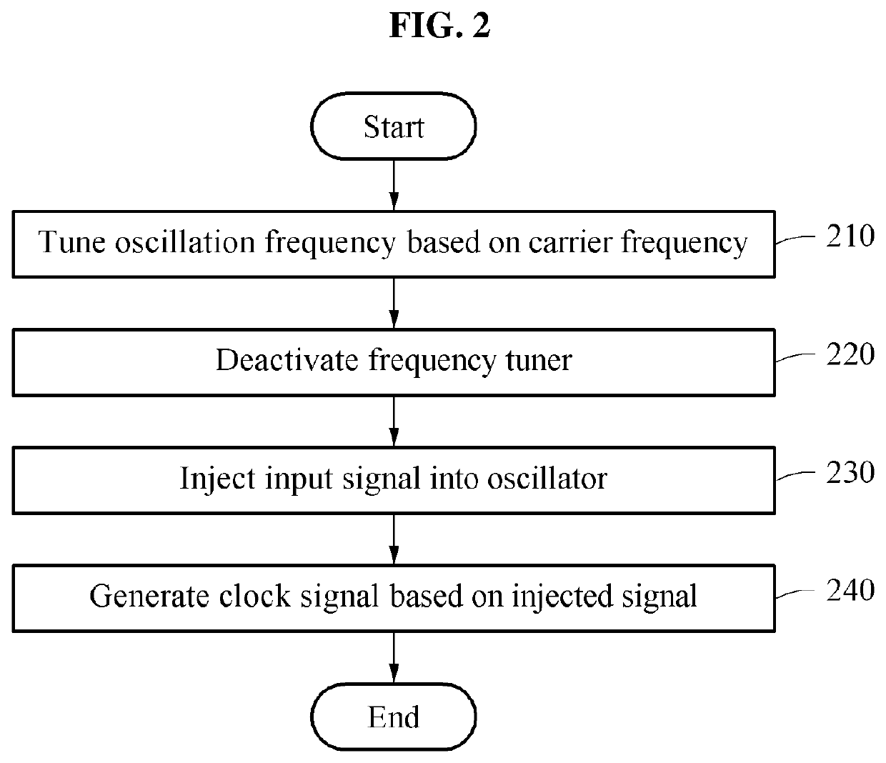
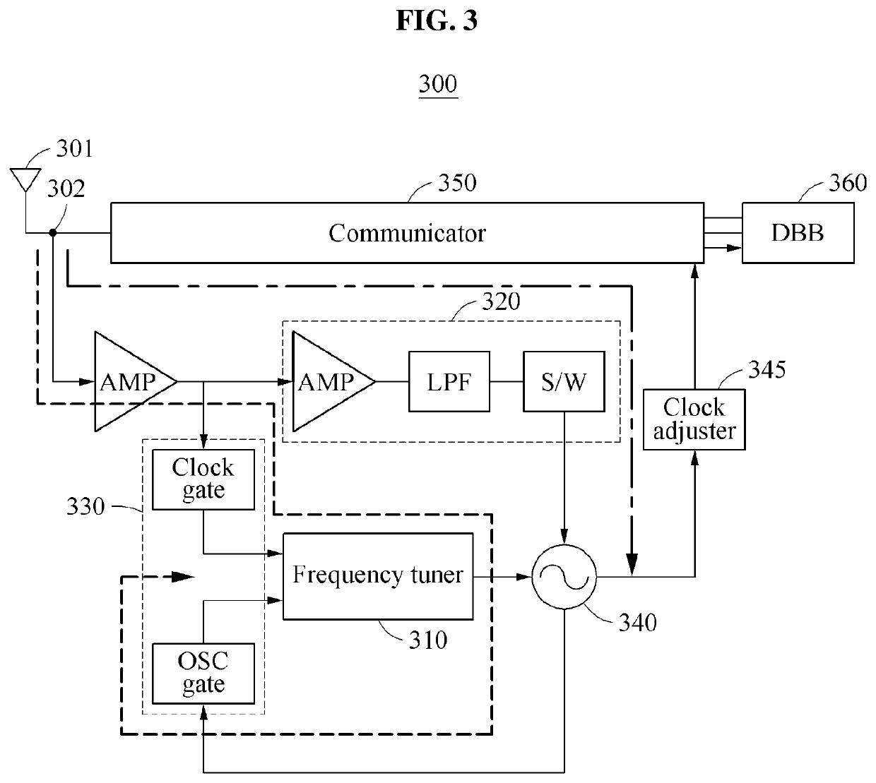
A clock frequency supply device includes: a frequency tuner configured to receive an input signal with a carrier frequency, and tune an oscillation frequency of an oscillator based on the carrier frequency; an injector configured to inject the input signal directly into the oscillator after the tuning of the oscillation frequency is completed; and an oscillator configured to generate a reference clock signal with a reference clock frequency based on the injected input signal.

Description

CROSS-REFERENCE TO RELATED APPLICATIONS[0001]This application claims the benefit under 35 USC § 119(a) of Korean Patent Application No. 10-2018-0162009 filed on Dec. 14, 2018 in the Korean Intellectual Property Office, the entire disclosure of which is incorporated herein by reference for all purposes.BACKGROUND1. Field[0002]The following description relates to a device and method with clock frequency supply.2. Description of Related Art[0003]In low-power wireless communications (for example, a wireless sensor node and a telemetry), the size and charge of a battery may be limited, and thus a super low-power wireless transceiver may be advantageous. In low-power wireless communications, a frequency synthesizer (for example, a phase locked loop (PLL) or a voltage-controlled oscillator (VCO)) may consume a majority of power used by a wireless transmission chip.SUMMARY[0004]This Summary is provided to introduce a selection of concepts in a simplified form that are further described belo...

Claims


Application Information

Patent Timeline
Patent Type & Authority Patents(United States)
IPC IPC(8): H03L7/089H04B5/00H04L7/033H04L27/02
CPCH03L7/0891H04B5/0062H04L7/0331H04L27/02H03L7/191H03L7/0991H03J2200/29H03J2200/28H03J9/02H03J2200/09H03L7/24H03L7/083H03L7/099H03L7/093H04B5/77
Inventor KIM, SEONG JOONG
Owner SAMSUNG ELECTRONICS CO LTD
Learn More