
3D object scanning method using structured light

a structured light and object technology, applied in the field of 3d object scanning method using structured light, can solve the problems of insufficient image processing, inability to improve accuracy, and inability to accurately reproduce the physical object as a 3d model and ease of use, and achieve the effect of reducing resolution, facilitating processing of generating the 3d model, and high resolution

Active Publication Date: 2021-02-02
GLOBAL SCANNING DENMARK AS
View PDF9 Cites 0 Cited by
  • Summary
  • Abstract
  • Description
  • Claims
  • Application Information

AI Technical Summary

Benefits of technology

The patent describes a method for accurately estimating the location of target positions on the surface of a physical object using image processing. By using a trained network, the accuracy of the location estimate is improved by using a higher resolution in the first images and ensuring consistent scanner settings during recording. This approach enables more accurate and efficient positioning in applications such as manufacturing processes.

Problems solved by technology

However, it is observed that the image processing, including the weighted arithmetic mean, is not sufficient to improve accuracy; at least not for all surface types of a 3D object.
Generally, prior art 3D object scanners requiring structured light typically suffers from one or both of a lack of accuracy in reproducing the physical object as a 3D model and ease of use.
One reason may be that the structured light impinging on the surface of object being scanned may be scattered in unpredictable ways and especially so when the surface across an area of an object varies.
Further, some 3D object scanners requiring structured light may be sensitive to light from the surroundings such as sunlight, which cannot be controlled by the scanner.
Even a small number of adjustable operational conditions unfortunately gives a high number of combinations which pushes especially an unexperienced user of a 3D scanner into a tedious trial-and-error process before an accurate point cloud or three-dimensional model of the surface of the physical object is accurately computed.
One or more of the above limitations may be an obstacle towards providing a 3D object scanner, using structured light, which can be used by a wider range of users or across a wider range of objects.
Experience and experiments have shown that it is very difficult even for an experienced user of a 3D scanner to obtain accurate or even useable scanning of physical objects with transparent or semi-transparent surfaces, structures or portions.
In either case, the user is relieved from a very time consuming task of adjusting operational conditions, typically by a trial-and-error process involving both scanning operations (time consuming) and digital reconstruction operations (also time consuming).
Thus, the user is not enabled to operatively set one or both of electrical working conditions for the light projector and optical working conditions for the light projector.

Method used


Image

  • 3D object scanning method using structured light
  • 3D object scanning method using structured light
  • 3D object scanning method using structured light

Examples


Embodiment Construction

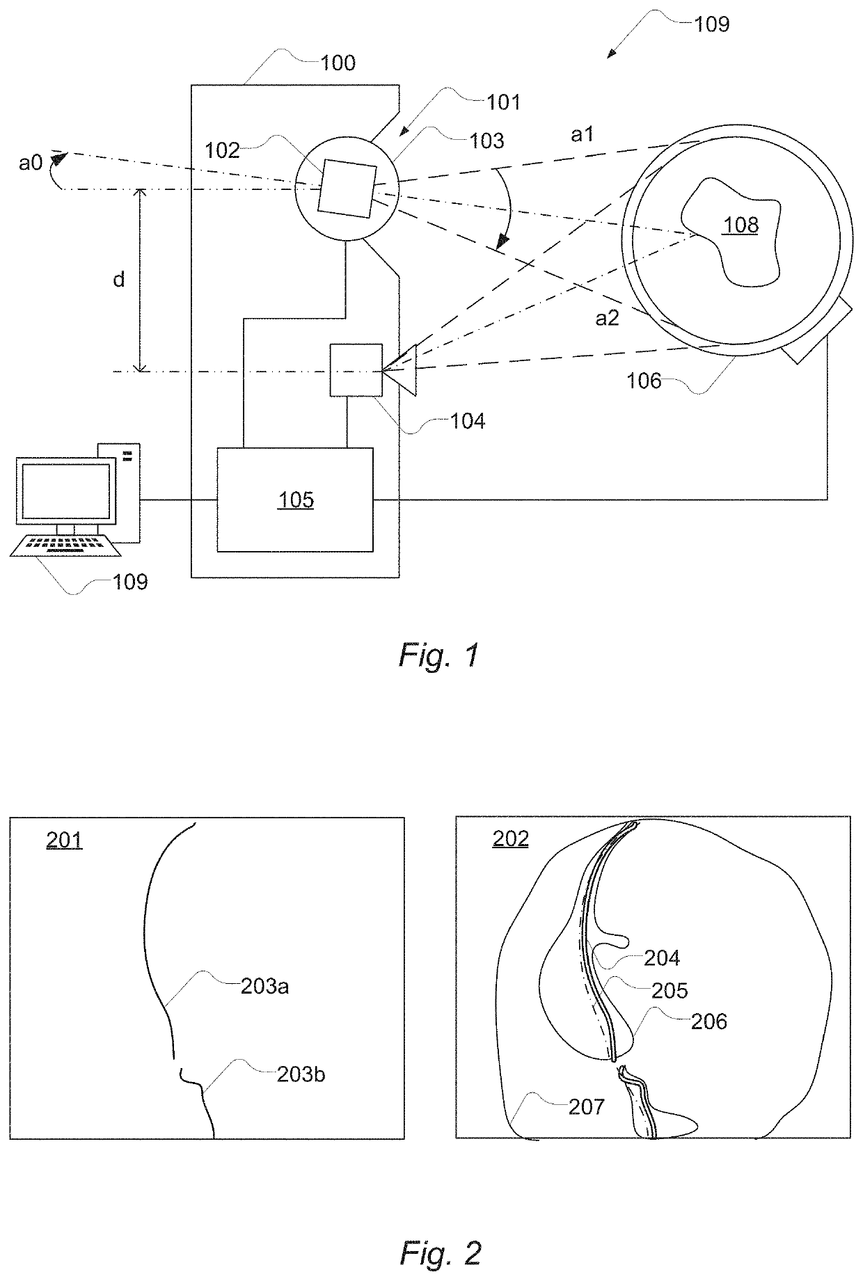
[0125]FIG. 1 shows a 3D scanner system comprising a 3D scanner 100 based on structured light. The 3D scanner 100 is coupled to a first computer 109 and an object turntable 106. In some examples, the 3D scanner 100, the first computer 109 and the object turntable 106 are integrated into a single device with a common housing.

[0126]As shown, the 3D scanner 100 comprises a light projector 101 configured to project structured light onto the surface of the physical object 108 and a camera 104 arranged at a distance, d, from the light projector 101 and at a viewing angle, a0, with respect to the light projector 101. The camera 104 is configured to record a sequence of first images of at least a portion of the surface of the physical object 108. The 3D scanner also comprises a controller 105 configured to control the light projector 101, the camera 104 and the object turntable 106. The controller may be configured to communicate with the first computer 109. The first computer 109 and the co...


PUM


Abstract

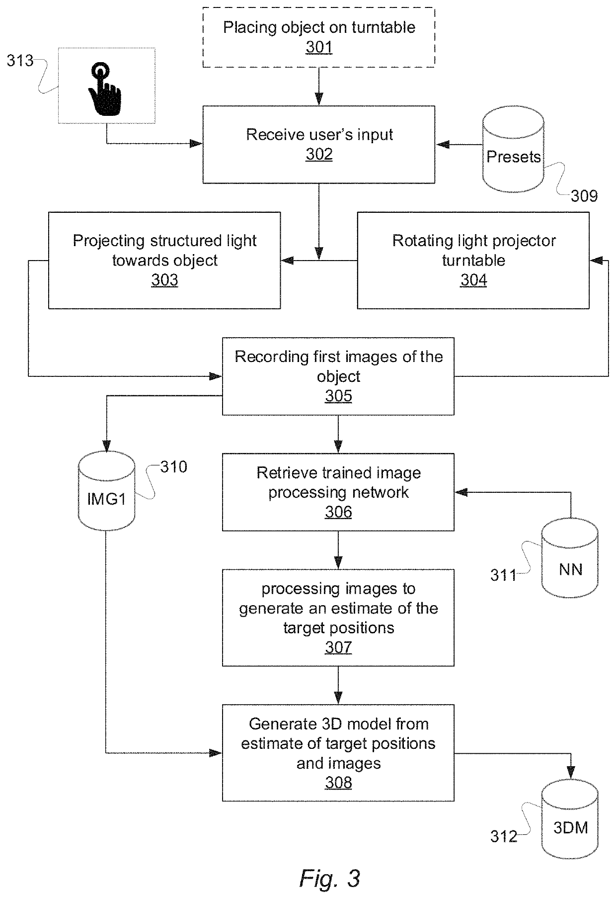
A method of scanning a 3D object includes: receiving a user's input to perform a scanning operation via a user interface, and in response using a light projector, projecting structured light onto the surface of a physical object about target positions on the surface of the physical object; and recording a sequence of first images of at least a portion of the surface of the physical object including a light scatter region illuminated by the structured light being projected about the target positions on the surface of the physical object using a camera. A trained image processing network configured during training to output data comprising a representation of positions being estimates of the target positions on the surface of the physical object in response to receiving one or more first images can be used.

Description

CROSS-REFERENCE TO RELATED APPLICATION[0001]This application claims priority to European Patent Application No. EP 18174872 filed on May 29, 2018, the disclosure of which including the specification, the drawings, and the claims is hereby incorporated by reference in its entirety.BACKGROUND OF THE INVENTION[0002]Conventional 3D, three-dimensional, object scanning for non-contacting measurement of the surface geometry of an object may in some examples be based on a light projector projecting a pattern of light, such as one or more lines, onto a 3D object (a physical object) and a camera recording images of the 3D object including the pattern of light. The pattern of light, such as a line, draws on the 3D object a curve of light which corresponds to a profile of the surface geometry of 3D object.[0003]One or more of the 3D object, the light projector and the camera may be moved by an actuator in a scanning movement to record multiple images to capture multiple projections of the light...

Claims


Application Information

Patent Timeline
Patent Type & Authority Patents(United States)
IPC IPC(8): G06T15/00G06T17/05G06T7/00G06T7/73G06T17/10G06T17/20
CPCG06T17/05G06T7/75G06T7/97G06T17/10G06T17/20G06T2200/04G06T2200/08G06T2207/10028G01B11/2433G01B11/25G06T7/521G06T2207/20084
Inventor ENGHOLM, NISVERHAEGH, GERARD
Owner GLOBAL SCANNING DENMARK AS
Learn More