
Method and a system for recovering thermal energy in a system comprising a chemical recovery boiler and a lime kiln

Active Publication Date: 2021-02-16
VALMET TECH OY
View PDF13 Cites 0 Cited by
  • Summary
  • Abstract
  • Description
  • Claims
  • Application Information

AI Technical Summary

Benefits of technology

The patent is about a solution for improving the efficiency of electricity production in a chemical recovery boiler. This is achieved by heating the feed water of the boiler using excess low-pressure steam from a steam turbine, which can then be used for other more important tasks. This results in more valuable low-pressure steam being used for productive purposes, rather than just heating the feed water. The solution also allows for the recovery and reuse of thermal energy from the flue gases of the lime kiln, further increasing energy efficiency.

Problems solved by technology

In both such example applications, and in comparable applications, there is a disadvantage in that the low-pressure steam such as steam bled off from the steam turbine reduces the electricity yield at the steam turbine.

Method used


Image

  • Method and a system for recovering thermal energy in a system comprising a chemical recovery boiler and a lime kiln
  • Method and a system for recovering thermal energy in a system comprising a chemical recovery boiler and a lime kiln
  • Method and a system for recovering thermal energy in a system comprising a chemical recovery boiler and a lime kiln

Examples


Embodiment Construction

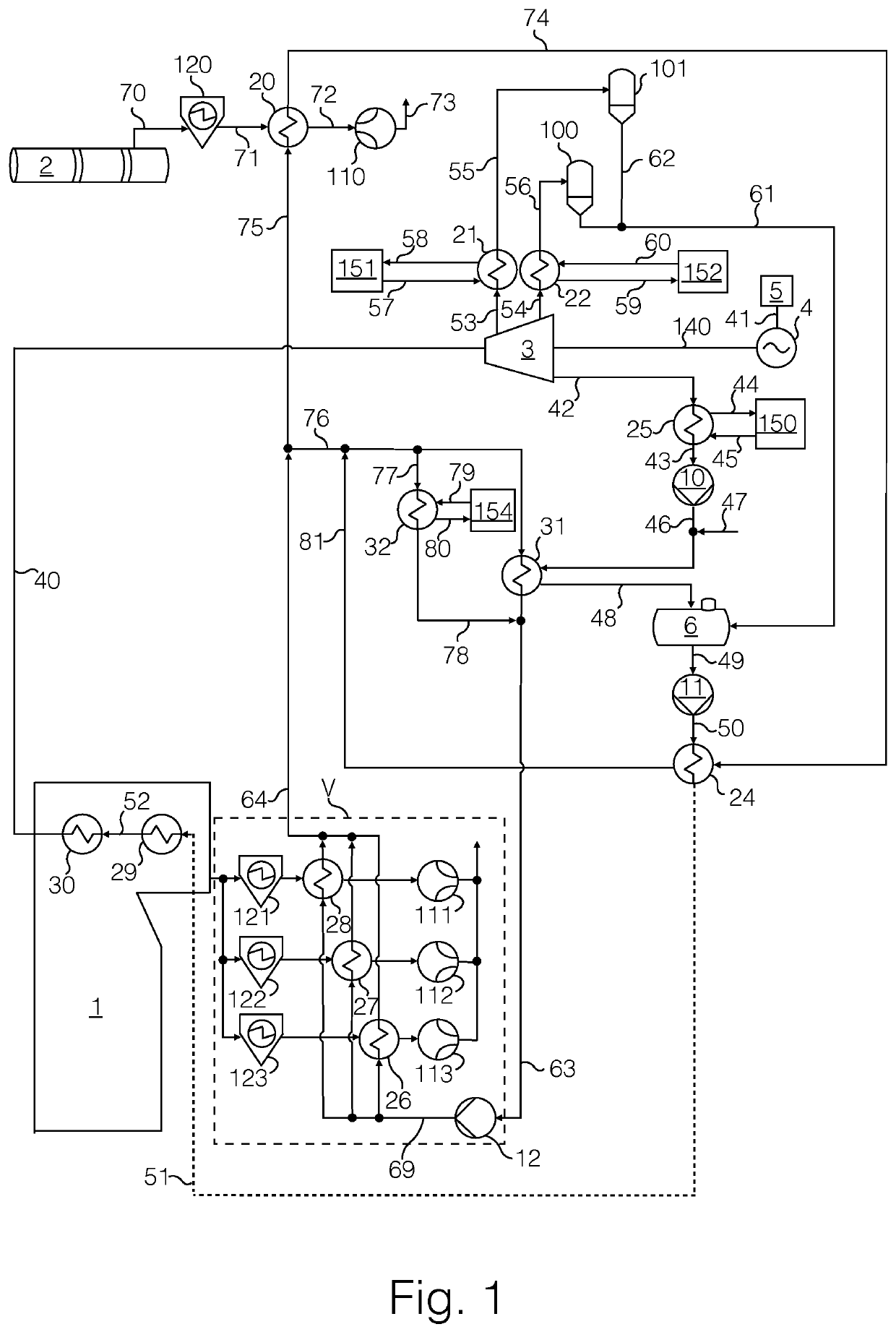
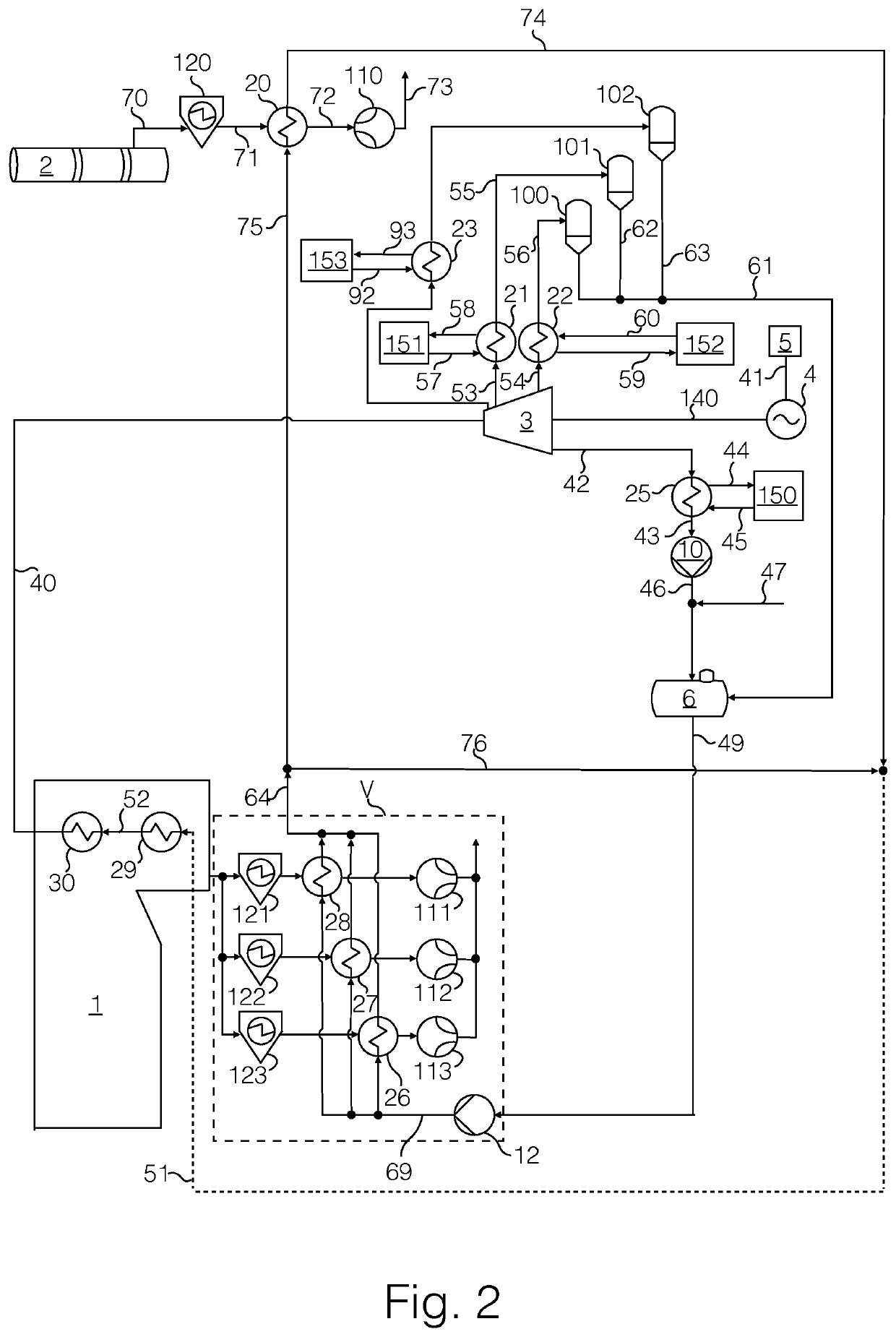
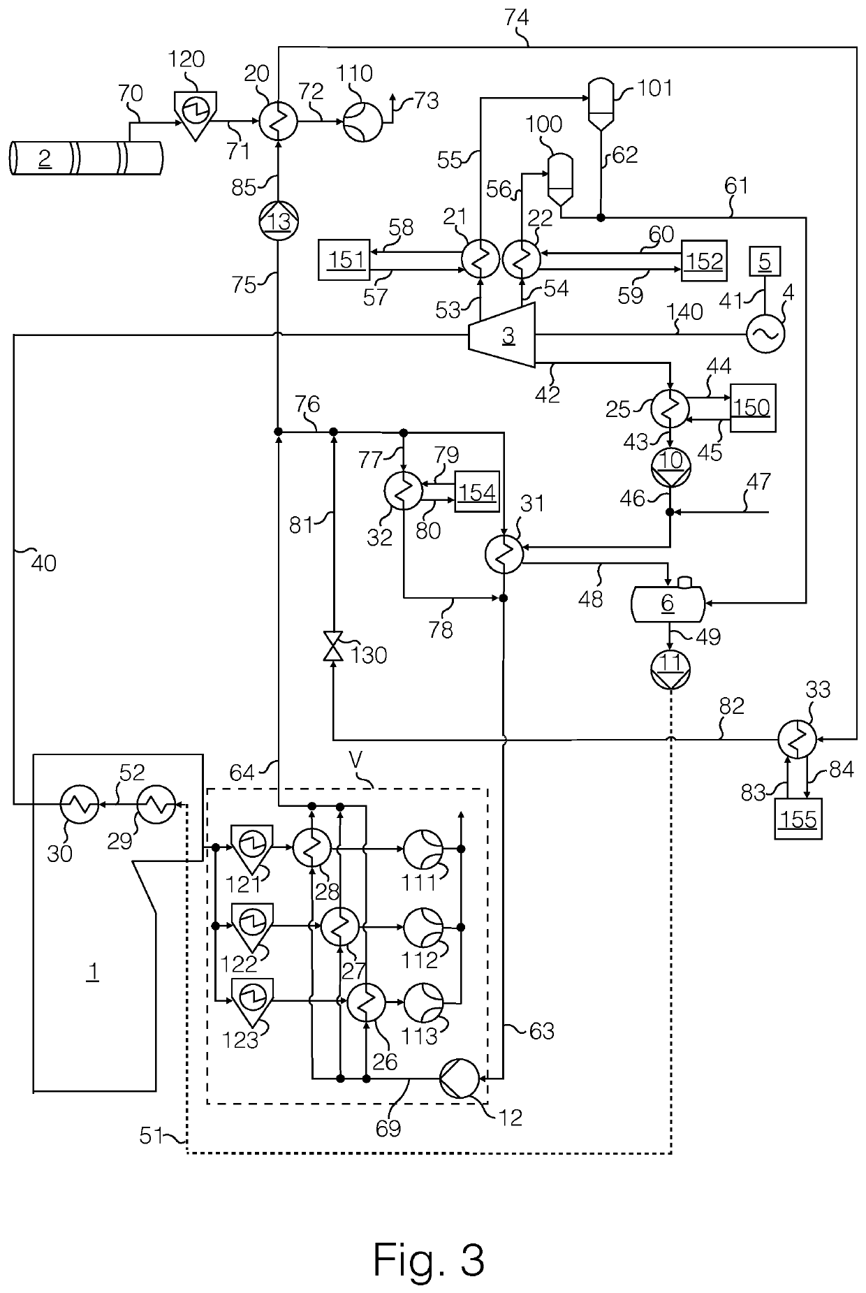
[0028]In the text, reference is made to the figures with the following numerals:[0029]1 Chemical recovery boiler[0030]2 Lime kiln[0031]3 Steam turbine[0032]4 Generator[0033]5 Electricity-consuming process[0034]6 Feed water tank[0035]7 First flue gas discharge channel[0036]8 Second flue discharge channel[0037]10 to 13 Pump[0038]20 to 35 Heat exchanger[0039]40 to 93 Line[0040]100 to 103 Flash tank[0041]110 to 113 Ejector pump[0042]120 to 123 Electrostatic precipitator[0043]130 to 131 Valve arrangement[0044]140 Driveline[0045]150 to 156 Heat-consuming process

[0046]In the text and in the figures, the notion of a “line” is used to refer to any suitable conveyance passageway without any definite characterization of the physical properties of the passageway. It is to be appreciated that a person skilled in the art is capable of determining the physical properties of a passageway according to the properties and the volume of the material to be conveyed as well as other such pertinent convey...


PUM


Abstract

Disclosed is a system for producing electricity, the system comprising a chemical recovery boiler adapted to supply superheated steam to a steam turbine driving a generator, the chemical recovery boiler comprising a first flue discharge channel with a first heat exchanger arrangement; and a lime kiln comprising a second flue discharge channel with a second heat exchanger arrangement; and a circulation for heat transfer medium between the said heat exchanger arrangements. Also disclosed is a method for producing electricity, wherein said heat transfer medium is circulated between said heat exchanger arrangements such that thermal energy may be transferred from the flue gases in the first flue charge channel and / or the second flue discharge channel into the feed water of the chemical recovery boiler and / or into a heat-consuming process.

Description

CROSS REFERENCE TO RELATED APPLICATIONS[0001]This application is a National Stage Application, filed under 35 U.S.C. § 371, of International Application No. PCT / FI2018 / 050870, filed Nov. 30, 2018, which claims priority to Finnish Application No. 20176111, filed Dec. 13, 2017; the contents of both of which as are hereby incorporated by reference in their entireties.BACKGROUNDRelated Field[0002]The solution relates electricity generation systems comprising a chemical recovery boiler and a lime kiln, and particularly to thermal energy recovery in such systems.DESCRIPTION OF RELATED ART[0003]In pulp manufacturing, chemical recovery boilers are employed to recover chemicals from the manufacturing process to be reused in the pulp manufacturing process. The process in the chemical recovery boiler generates heat which is typically used to produce superheated steam which is converted into electricity with steam turbine(s). In addition, from such a process comprising a chemical recovery boile...

Claims


Application Information

Patent Timeline
IPC IPC(8): F01K11/02F01N5/02H02K7/18
CPCF01K11/02F01N5/02H02K7/1823F01K13/00F01K21/00F01K27/00Y02E20/14Y02P40/40D21C11/12F22D1/32
Inventor MANSIKKASALO, JARMO
Owner VALMET TECH OY
Learn More