Moving an entire nuclear reactor core as a unitary structure

a nuclear reactor and core technology, applied in nuclear reactors, nuclear elements, greenhouse gas reduction, etc., can solve the problems of long unit refueling outages, square fuel assemblies, cumbersome and time-consuming processes, etc., and achieve the effect of increasing the service or cycle life of nuclear fuel supply

Active Publication Date: 2021-02-16
SMR INVENTEC
View PDF20 Cites 0 Cited by
  • Summary
  • Abstract
  • Description
  • Claims
  • Application Information

AI Technical Summary

Benefits of technology

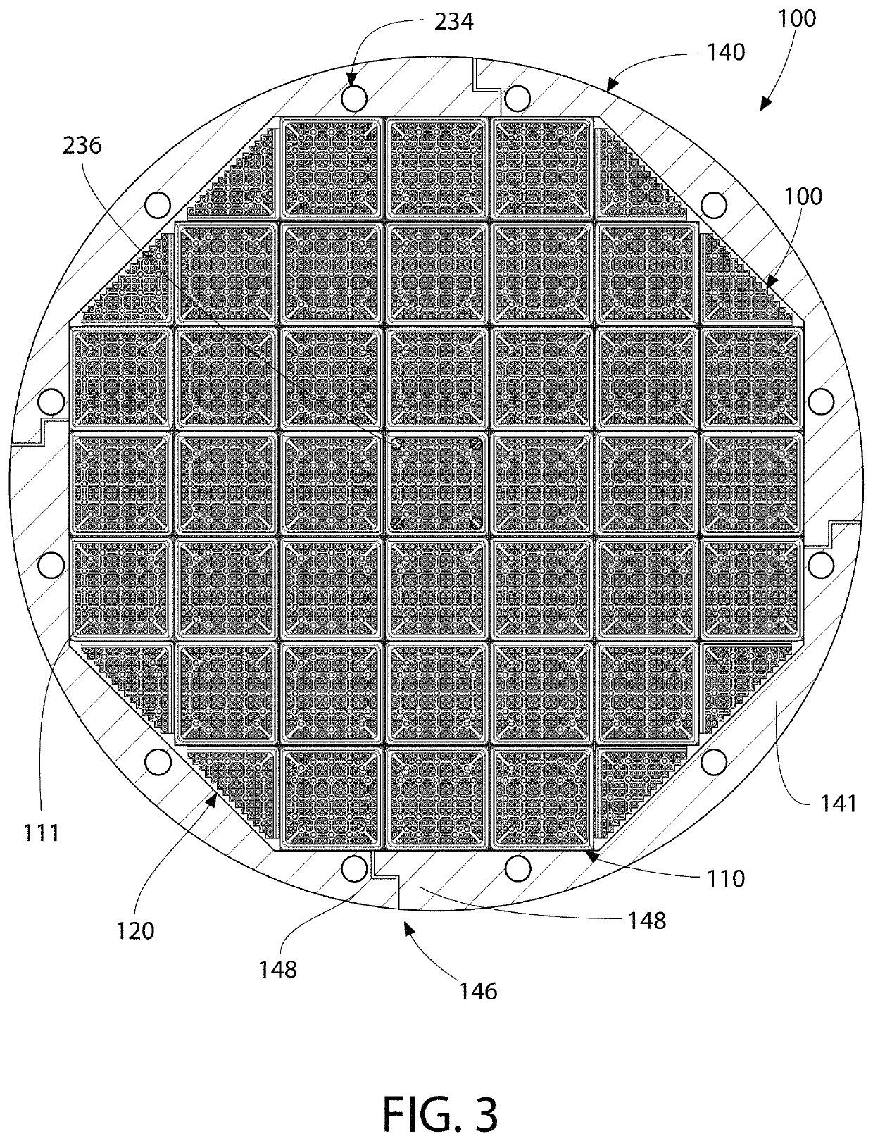
[0006]In one aspect, an improved nuclear reactor core is provided that utilizes nuclear fuel assemblies having two different transverse cross-sectional configurations. The nuclear fuel assemblies having two different transverse cross-sectional configurations are arranged in a pattern that, compared to existing nuclear reactor cores, takes advantage of peripheral corner regions that are formed between the fuel core and the reflector cylinder (which is generally a tubular structure that circumferentially surrounds the nuclear fuel core). In nuclear reactor cores that utilize nuclear fuel assemblies having only one cross-sectional configuration, such peripheral corner regions are left empty as they are too small to accommodate one of the nuclear fuel assemblies. By creating the nuclear reactor with nuclear fuel assemblies having at least two different transverse cross-sectional configurations, nuclear fuel assemblies can be provided in these peripheral corner spaces that were previously left empty, thereby providing a nuclear reactor core that makes optimum use of the available nuclear reactor core space to increase the service or cycle life of the nuclear fuel supply.
[0008]Calculations show that by adding the partial fuel assemblies, the cycle life of the nuclear fuel core may be increased by approximately four months in some embodiments. An even greater increase in the cycle life, as much as an additional four months, may be realized by coasting at a reduced operating power level, say approximately 90% of normal power, in the last few months of the cycle. This stretch power approach directly helps in nuclear fuel utilization (through higher burn-up). Accordingly, the partial fuel assemblies advantageously support such convenient power stretching strategies.
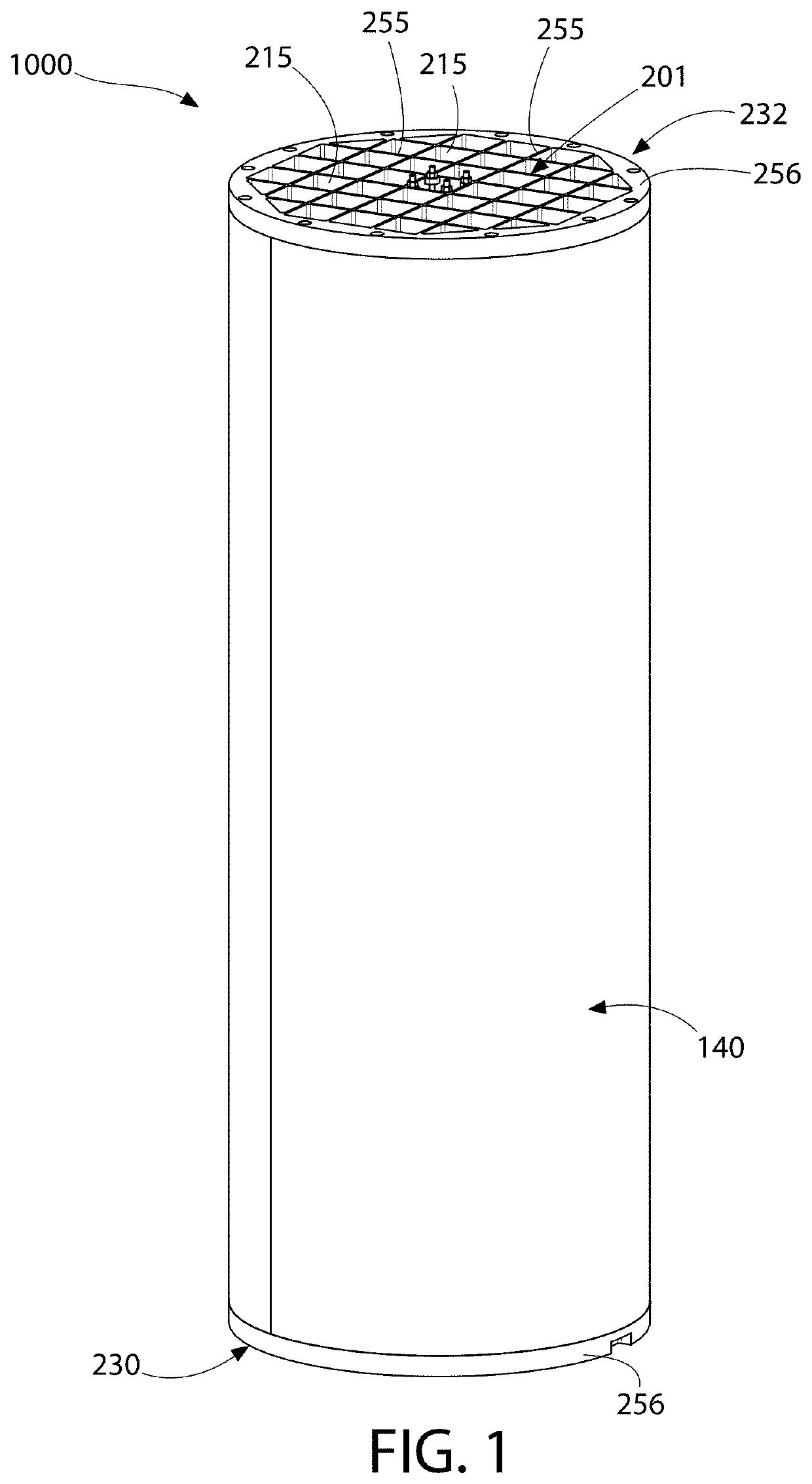
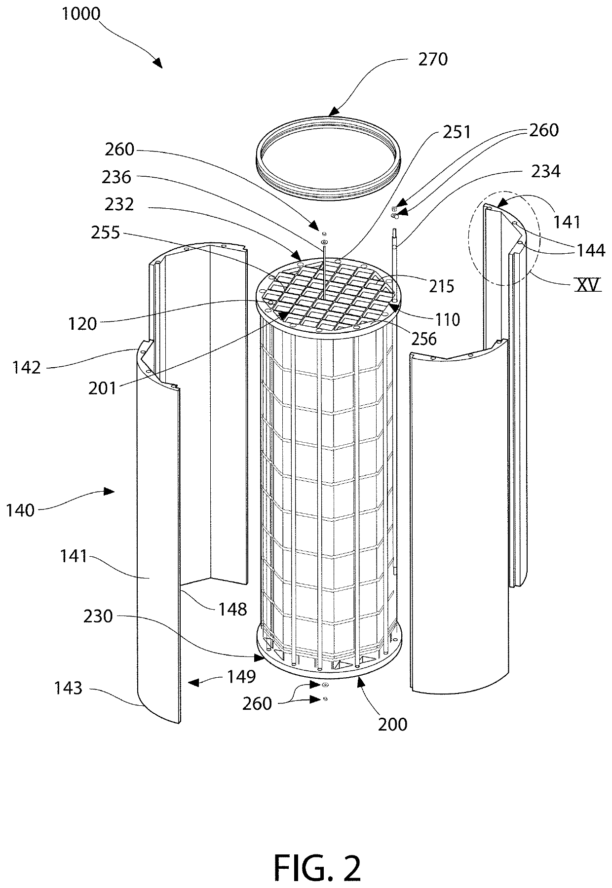
[0012]In another aspect, a portable nuclear fuel cartridge is provided that allows a nuclear reactor to be completely fueled and / or defueled by loading and / or unloading a self-supporting assemblage as a single unit. The portable nuclear fuel cartridge includes a unitary support structure and an integrated nuclear fuel core that is configured to be insertable into and removable from a nuclear reactor vessel as a self-contained and self-supporting unit, thereby forming a complete and highly portable nuclear fuel core. Accordingly, embodiments of the present invention include a portable nuclear fuel cartridge which is self-supporting and free standing outside of the nuclear reactor vessel with all of the nuclear fuel assemblies completely pre-installed. The integrated nuclear fuel core may comprise all of the nuclear fuel assemblies required to operate the nuclear reactor.
[0014]The portable nuclear fuel cartridge may be preassembled outside of the nuclear reactor vessel with all nuclear fuel assemblies intact, and then inserted into the nuclear reactor vessel. When the fuel supply is depleted, the entire portable nuclear fuel cartridge may be readily removed from the nuclear reactor vessel and a new complete and preassembled portable nuclear fuel cartridge may be inserted in its place. Advantageously, this negates the need to handle individual nuclear fuel assemblies on-site in piecemeal fashion to significantly reduce nuclear unit downtime for refueling. The portable nuclear fuel cartridge is constructed to be lifted, transported, installed, and stored as self-supporting and free-standing. In essence, the portable nuclear fuel cartridge serves as a “cradle-to-grave” structure from fueling a nuclear reactor to long-term storage.

Problems solved by technology

Heretofore, in prior systems, each of the nuclear fuel assemblies are handled individually and loaded / unloaded from the stationary nuclear reactor located inside the reactor vessel one at a time, which has proved to be a cumbersome and time consuming process.
As can be imagined, this process requires lengthy unit refueling outages to complete all of the necessary nuclear fuel assembly replacements.
The square shaped fuel assemblies however, are not conducive to making efficient use of all available space within the core circumscribed by the reflector leaving unused regions between the core and reflector.

Method used


Image

  • Moving an entire nuclear reactor core as a unitary structure
  • Moving an entire nuclear reactor core as a unitary structure
  • Moving an entire nuclear reactor core as a unitary structure

Examples


Embodiment Construction

[0044]The features and benefits of the present disclosure are illustrated and described herein by reference to exemplary embodiments. This description of exemplary embodiments is intended to be read in connection with the accompanying drawings, which are to be considered part of the entire written description. Accordingly, the present disclosure expressly should not be limited to such embodiments illustrating some possible non-limiting combination of features that may exist alone or in other combinations of features; the scope of the claimed invention being defined by the claims appended hereto.

[0045]In the description of embodiments disclosed herein, any reference to direction or orientation is merely intended for convenience of description and is not intended in any way to limit the scope of the present invention. Relative terms such as “lower,”“upper,”“horizontal,”“vertical,”, “above,”“below,”“up,”“down,”“top” and “bottom” as well as derivative thereof (e.g., “horizontally,”“down...


PUM

PropertyMeasurementUnit
physical spaceaaaaaaaaaa
shapeaaaaaaaaaa
stretch poweraaaaaaaaaa

Abstract

An entire nuclear fuel core comprising a plurality of fuel assemblies is preassembled in a nuclear fuel cartridge having a self-supporting unitary support structure. During a refueling operation, the unitary support structure is moved into a nuclear reactor vessel. The unitary support structure may be formed by top and bottom core plates coupled together by vertically-oriented connecting rods which compress the fuel assemblies therebetween. A plurality of reflector wall segments circumscribe the core and are the coupled together between the core plates by the connecting rods which are coupled to the core plates. The connecting rods may extend through the wall segments.

Description

CROSS-REFERENCE TO RELATED PATENT APPLICATIONS[0001]The present application is a continuation of U.S. patent application Ser. No. 14 / 413,807 filed Jan. 9, 2015, which is a U.S. national stage application under 35 U.S.C. § 371 of PCT Application No. PCT / US2013 / 049722 filed Jul. 9, 2013, which claims the benefit of U.S. Provisional Patent Application No. 61 / 669,428 filed Jul. 9, 2012; the entireties of which are incorporated herein by reference.FIELD OF THE INVENTION[0002]The present invention elates generally to nuclear reactors and methods and apparatus of fueling and defueling the same, and more specifically to an optimized arrangement of fuel assemblies in a nuclear reactor core and / or a portable nuclear fuel cartridge.BACKGROUND OF THE INVENTION[0003]A typical nuclear reactor core in a light water reactor comprises tightly packed “nuclear fuel assemblies” (also referred to as nuclear fuel bundles) of square cross section. Each nuclear fuel assembly is an assemblage of multiple “n...

Claims


Application Information

Patent Timeline
Patent Type & Authority Patents(United States)
IPC IPC(8): G21C5/06G21C3/30G21C5/14G21C11/06G21C19/19G21C1/06G21C3/32G21C19/07G21C19/18G21C3/33
CPCG21C5/06G21C3/30G21C5/14G21C11/06G21C19/19G21C1/06G21C3/32G21C3/3315G21C19/07G21C19/18Y02E30/30Y10T29/49947G21F5/012G21F5/14G21C19/32G21F5/008
Inventor SINGH, KRISHNA P.ANTON, P. STEFANSTEFANOVIC, PETER
Owner SMR INVENTEC
Why Eureka
Try Eureka