Braking apparatus and method for vehicle

a technology for braking apparatus and vehicles, applied in the direction of pulse generators, braking systems, pulse techniques, etc., can solve the problems of increasing manufacturing costs and and achieve the effect of reducing the manufacturing cost of the vehicle and removing the operating noise of bls

Active Publication Date: 2021-02-23
HYUNDAI MOBIS CO LTD
View PDF23 Cites 0 Cited by
  • Summary
  • Abstract
  • Description
  • Claims
  • Application Information

AI Technical Summary

Benefits of technology

[0008]Embodiments of the present invention are directed to a braking apparatus and method for a vehicle, which can solve the problems such as an occurrence of operating noise and an increase in manufacturing cost which are caused by the configuration in which a pedal stroke sensor and a BLS are installed as separate modules.
[0016]In accordance with the embodiment of the present invention, the function of the conventional BLS may be implemented in a circuit manner through the configuration in which the braking of the vehicle and the turn-on / off of the brake lamp are implemented together based on the output signal from the pedal stroke sensor, which makes it possible to not only remove operating noise of the BLS implemented as a mechanical switch, but also reduce the manufacturing cost of the vehicle.

Problems solved by technology

That is, since the existing BLS is implemented as a mechanical switch, the BLS may generate operating noise.
Furthermore, since the pedal stroke sensor and the BLS are configured as separate modules, a wire harness and a PCB (Printed Circuit Board) are doubly applied, thereby increasing the manufacturing cost.

Method used


Image

  • Braking apparatus and method for vehicle
  • Braking apparatus and method for vehicle
  • Braking apparatus and method for vehicle

Examples


Embodiment Construction

[0020]Hereafter, a braking apparatus and method for a vehicle in accordance with an embodiment of the present invention will be described in detail with reference to the accompanying drawings. It should be noted that the drawings are not to precise scale and may be exaggerated in thickness of lines or sizes of components for descriptive convenience and clarity only. Furthermore, the terms as used herein are defined by taking functions of the invention into account and can be changed according to the custom or intention of users or operators. Therefore, definition of the terms should be made according to the overall disclosures set forth herein.

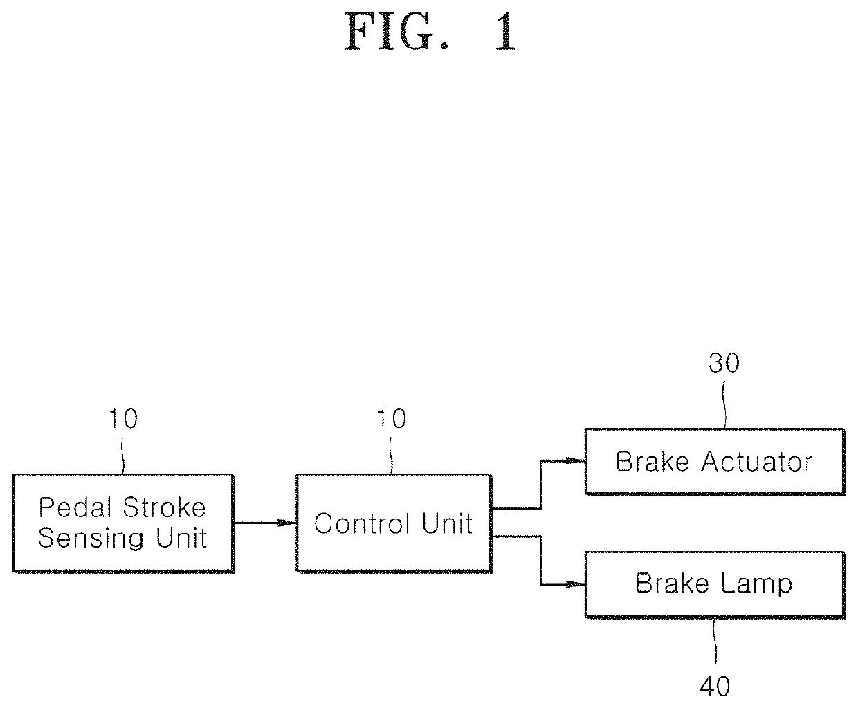
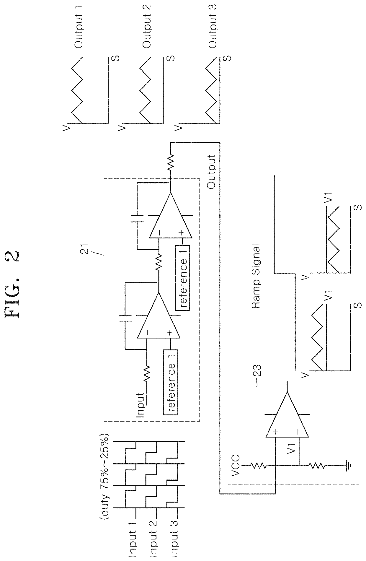
[0021]FIG. 1 is a block diagram illustrating a braking apparatus for a vehicle in accordance with an embodiment of the present invention, and FIG. 2 is a circuit diagram illustrating a detailed circuit configuration of a control unit in the braking apparatus for a vehicle in accordance with the embodiment of the present invention.

[0022]Referri...


PUM


Abstract

A braking apparatus for a vehicle may include: a pedal stroke sensing unit configured to sense a pedal stroke of a brake pedal, and output a pedal stroke signal; and a control unit configured to control a brake actuator for braking the vehicle, based on the pedal stroke signal inputted from the pedal stroke sensing unit, and output a ramp signal in which information on whether a braking action of the vehicle has been performed is reflected, based on a reference voltage signal which is preset to determine whether the brake pedal is stepped on and a voltage signal converted from the pedal stroke signal.

Description

CROSS-REFERENCES TO RELATED APPLICATIONS[0001]The present application claims priority to Korean application number 10-2018-0095215, filed on Aug. 16, 2018, which is incorporated by reference in its entirety.BACKGROUND OF THE INVENTION[0002]The present invention relates to a braking apparatus and method for a vehicle, and more particularly, to a braking apparatus and method for a vehicle, which can control a brake actuator and a brake lamp of a vehicle.[0003]Recently, an electric booster brake system has spread to implement a vacuum-free brake system for improving fuel efficiency and to implement regenerative brake cooperation control of an electric vehicle and an active brake actuator such as an autonomous emergency braking system (AEB).[0004]In general, the electric booster brake system maintains most of the brake mechanism of an existing vacuum booster brake system, but has a difference in boosting mechanism from the vacuum booster brake system in that the electric booster brake s...

Claims


Application Information

Patent Timeline
Patent Type & Authority Patents(United States)
IPC IPC(8): B60Q1/44B60T7/04B60T13/74H03K7/08
CPCB60Q1/441B60T7/042B60T13/74H03K7/08B60T7/06H03K4/066B60T8/3255B60T13/662B60T17/22B60T2220/04B60T13/741
Inventor PARK, JAE HYUN
Owner HYUNDAI MOBIS CO LTD
Why Eureka
Try Eureka