Supercharge Your Innovation With Domain-Expert AI Agents!

Display method and display system for reducing a double image effect

a display system and image effect technology, applied in static indicating devices, instruments, cathode-ray tube indicators, etc., can solve the problems of reducing image quality, user can see a transient effect of unstable pixels, and reducing visual quality, so as to reduce the effect of double image

Active Publication Date: 2021-02-23
BENQ INTELLIGENT TECH SHANGHAICO LTD +1
View PDF10 Cites 1 Cited by
  • Summary
  • Abstract
  • Description
  • Claims
  • Application Information

AI Technical Summary

Benefits of technology

This approach effectively minimizes double image effects and maintains sufficient image brightness by ensuring pixels are refreshed and displayed in a stable state, enhancing visual quality and reducing eye strain.

Problems solved by technology

In the conventional display device, a user easily feels an image flickering effect when the image is displayed, thereby reducing the visual quality.
Also, when the image belongs to a high-speed dynamic image and is displayed by using the screen with a high refresh frequency, a motion blur effect easily occurs, leading to reduced image quality.
Further, the user can see a transient effect of unstable pixels when the image is in the process of refreshing their pixel polarities during the time interval of the backlight source being enabled.
Therefore, it is easy for the user to see an unpleasant image flickering effect or a double image effect.
Moreover, even if the user does not notice the image flickering effect of the screen when a high-speed image flickering effect or a high-frequency image flickering effect occurs, the user may unconsciously feel tired or suffer from permanent vision damage after watching flickering images for a long time.
However, the optimized pulse modulation signal may not be supported by the display device.
As a result, the visual quality may be decreased.

Method used


Image

  • Display method and display system for reducing a double image effect
  • Display method and display system for reducing a double image effect
  • Display method and display system for reducing a double image effect

Examples


Embodiment Construction

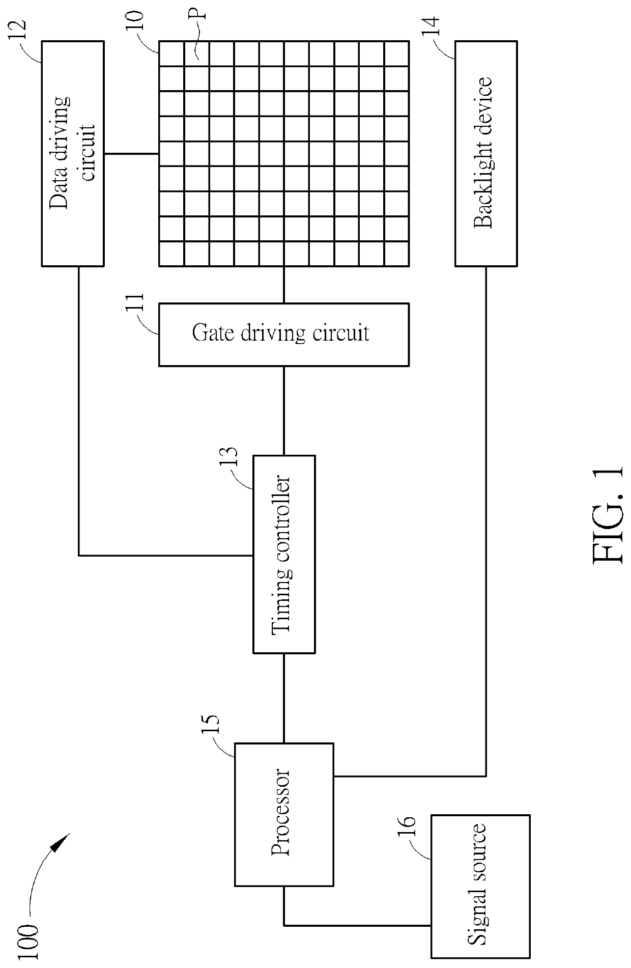
[0013]FIG. 1 is a block diagram of a display system 100 according to an embodiment of the present invention. The display system 100 includes a display panel 10, a gate driving circuit 11, a data driving circuit 12, a timing controller 13, a backlight device 14, and a processor 15. The display panel 10 can be any panel type of display panels, such as a liquid crystal display (LCD) panel or an organic light emitting diode display panel. The display panel 10 includes a plurality of pixels P for displaying an image. The plurality of pixels P can form a pixel array to display the image with a rectangular shape. The gate driving circuit 11 is coupled to the plurality of pixels P for controlling the plurality of pixels P by using gate voltages. The gate voltages can control the plurality of pixels P by using a row by row scanning process for enabling or disabling the pixels P. The data driving circuit 12 is coupled to the plurality of pixels P for inputting data signals to the plurality of...


PUM


Abstract

A display method includes changing a first transmission rate of a panel data clock signal to a second transmission rate, changing a first vertical synchronization period of a vertical synchronization signal to a second vertical synchronization period including a vertical pixel active synchronization interval and a blank interval according to at least the second transmission rate of the panel data clock signal, and merely enabling a backlight device during a time interval of any length within the blank interval. The second transmission rate is greater than the first transmission rate. The second vertical synchronization period is greater than the first vertical synchronization period.

Description

BACKGROUND OF THE INVENTION1. Field of the Invention[0001]The present invention illustrates a display method and a display system for reducing a double image effect, and more particularly, a display method and a display system for reducing the double image effect by maximizing a length of a vertical synchronization period.2. Description of the Prior Art[0002]Liquid crystal display (LCD) devices and organic light emitting diode (OLED) devices have been widely used in our daily life because they take several advantages of thin appearance, low power consumption, and no radiation. For example, the LCD devices and OLED devices can be applied to multimedia players, mobile phones, personal digital assistants, computer monitors, or flat-screen TVs.[0003]A conventional display device uses a pulse width modulation signal for driving a backlight source when images are displayed on a screen. The backlight source is enabled or disabled during a time interval greater than an image frame duration ...

Claims


Application Information

Patent Timeline
Patent Type & Authority Patents(United States)
IPC IPC(8): G09G5/18G09G5/10
CPCG09G5/18G09G5/10G09G2310/0237G09G2310/08G09G3/34G09G3/3406G09G2320/064G09G5/008G09G2320/0247G09G2340/0435G09G2320/0257G09G2320/0261
Inventor LIN, HSIN-NAN
Owner BENQ INTELLIGENT TECH SHANGHAICO LTD
Features
  • R&D
  • Intellectual Property
  • Life Sciences
  • Materials
  • Tech Scout
  • Unparalleled Data Quality
  • Higher Quality Content
  • 60% Fewer Hallucinations
Learn More