
Coherent optical receiver

Active Publication Date: 2021-03-09
ELENION TECH LLC
View PDF15 Cites 1 Cited by
  • Summary
  • Abstract
  • Description
  • Claims
  • Application Information

AI Technical Summary

Benefits of technology

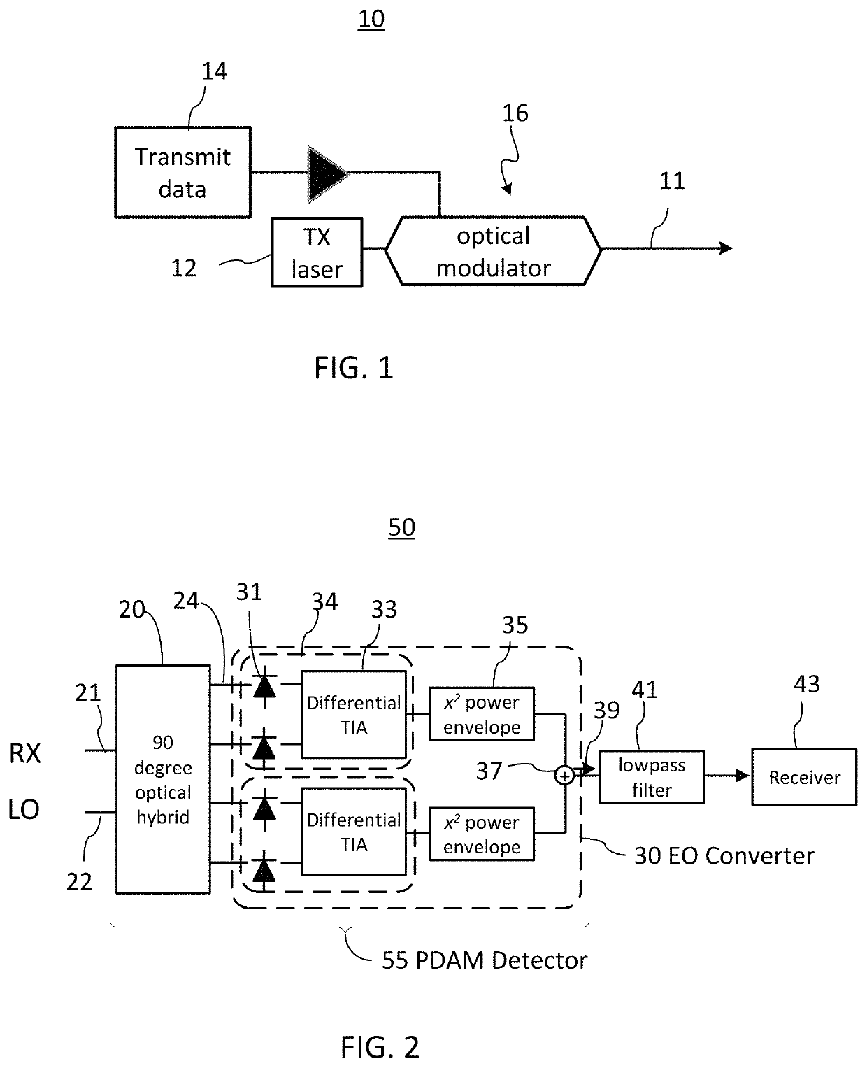
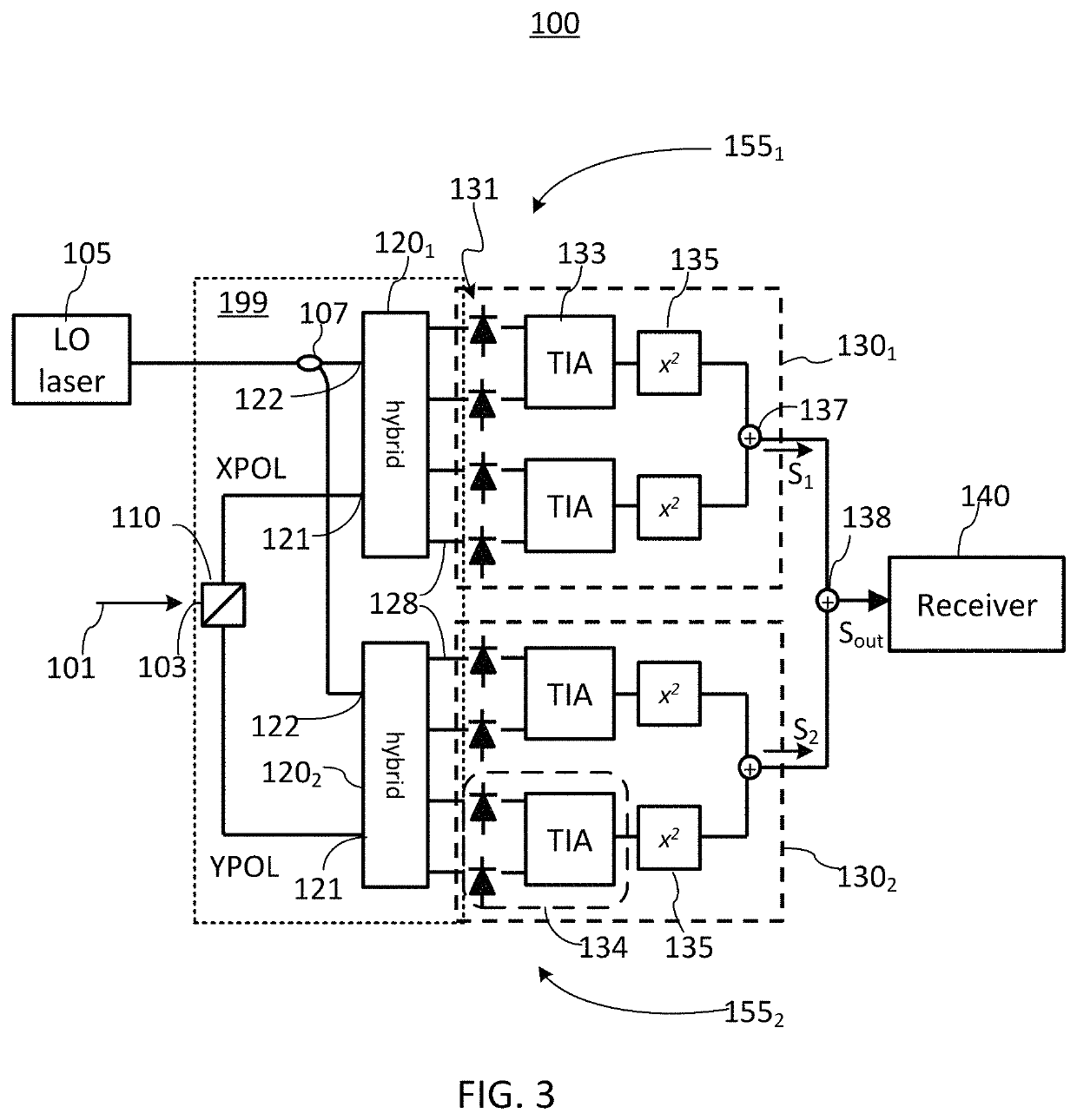
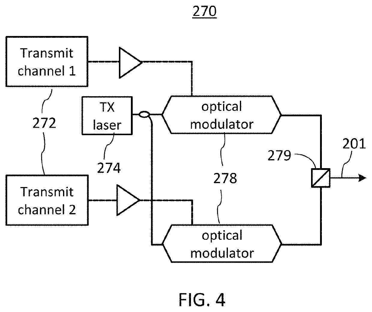
This patent describes a new type of optical receiver that can detect and measure the amplitude of light. It uses a special device called a polarization beam splitter to split the light into two different polarizations, and a special optical hybrid to mix the two polarizations together. The light is then detected by two different optical receivers, each with its own laser and amplifier. The device can measure the amplitude of the light with high accuracy, making it useful for various applications such as optical communications.

Problems solved by technology

For longer distances, direct-detection communication systems suffer from increased noise at the receiver due to a high optical fiber loss, which may result in an unacceptable Bit Error Rate (BER).
Optical amplifiers can be used to boost optical signal power at the receiver and to provide increased receiver sensitivity, which however increases the cost and complexity of the communication link.
This signal processing may be relatively complex and thus typically requires digital signal processors (DSPs) that are relatively power-consuming and expansive.
Accordingly, it may be understood that there may be significant problems and shortcomings associated with current solutions and technologies for reliably receiving high-bandwidth optical signals at relatively long distances.

Method used


Image

  • Coherent optical receiver
  • Coherent optical receiver
  • Coherent optical receiver

Examples


Embodiment Construction

[0022]In the following description, for purposes of explanation and not limitation, specific details are set forth, such as particular optical circuits, circuit components, techniques, etc. in order to provide a thorough understanding of the present invention. However, it will be apparent to one skilled in the art that the present invention may be practiced in other embodiments that depart from these specific details. In other instances, detailed descriptions of well-known methods, devices, and circuits are omitted so as not to obscure the description of the present invention. All statements herein reciting principles, aspects, and embodiments of the invention, as well as specific examples thereof, are intended to encompass both structural and functional equivalents thereof. Additionally, it is intended that such equivalents include both currently known equivalents as well as equivalents developed in the future, i.e., any elements developed that perform the same function, regardless...


PUM


Abstract

A coherent optical receiver for AM optical signals has a photonic integrated circuit (PIC) as an optical front-end. The PIC includes a polarization beam splitter followed by two optical hybrids each followed by an opto-electric (OE) converter. Each OE converter includes one or more differential detectors and one or more squaring circuits, which outputs may be summed. The PIC may further include integrated polarization controllers, wavelength demultiplexers, and / or tunable dispersion compensators.

Description

TECHNICAL FIELD[0001]The invention generally relates to coherent optical receivers, and more particularly relates to coherent optical receivers for amplitude modulated (AM) optical signals.BACKGROUND[0002]Direct detect communication techniques provide relatively simple and low-power solutions to optical transmission over short distances. For longer distances, direct-detection communication systems suffer from increased noise at the receiver due to a high optical fiber loss, which may result in an unacceptable Bit Error Rate (BER). Optical amplifiers can be used to boost optical signal power at the receiver and to provide increased receiver sensitivity, which however increases the cost and complexity of the communication link.[0003]Coherent optical receivers include a laser source acting as a local oscillator (LO), which boosts the received signal power through coherent mixing. The phase of the LO light relative to the received light signal is however typically unknown, and digital s...

Claims


Application Information

Patent Timeline
IPC IPC(8): H04B10/61H04B10/532G02B6/293G02F1/225H04B10/67G02F1/21
CPCH04B10/614G02B6/2935G02B6/29395G02F1/225H04B10/532H04B10/612H04B10/6161H04B10/65H04B10/676G02F2001/212G02B6/4213G02F1/212
Inventor YOUNCE, RICHARD C.RYLYAKOV, ALEXANDERHOCHBERG, MICHAEL J.
Owner ELENION TECH LLC
Learn More