
Vehicle exhaust system

a technology of exhaust gas and exhaust pipe, which is applied in the direction of engines, mechanical equipment, machines/engines, etc., can solve the problem of limiting the fluidity of exhaust gas

Active Publication Date: 2021-03-16
HYUNDAI MOTOR CO LTD +1
View PDF26 Cites 4 Cited by
  • Summary
  • Abstract
  • Description
  • Claims
  • Application Information

AI Technical Summary

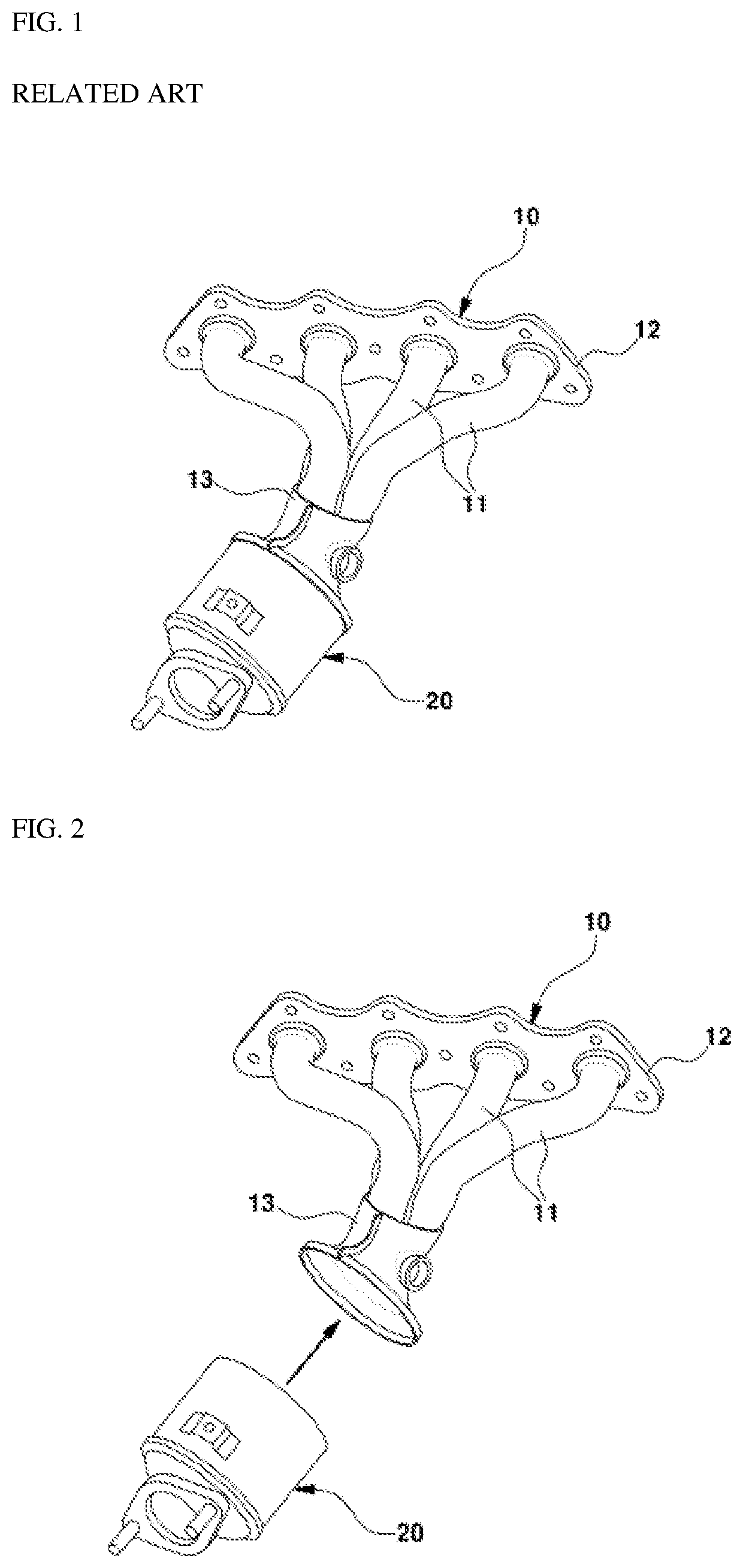
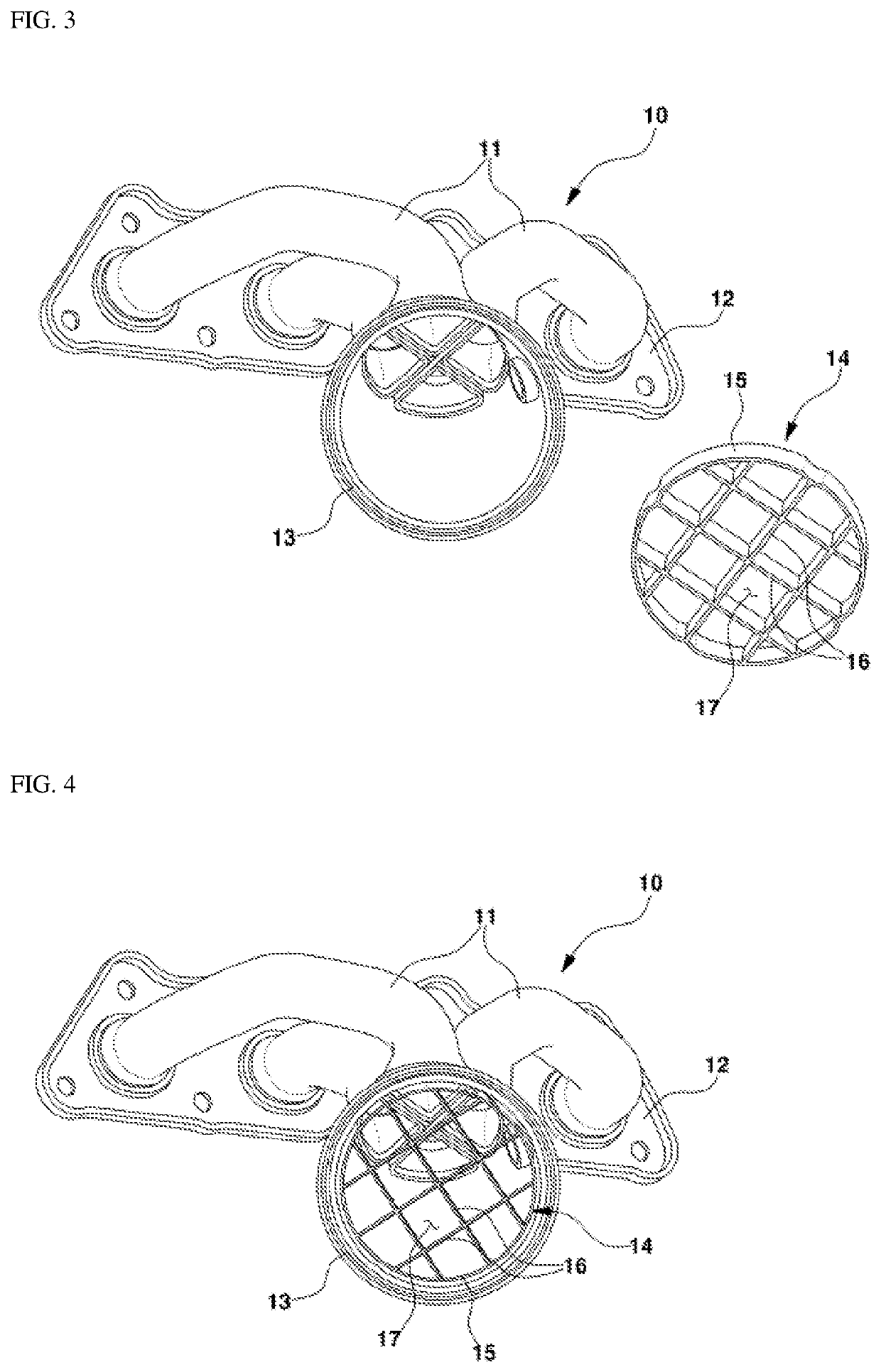
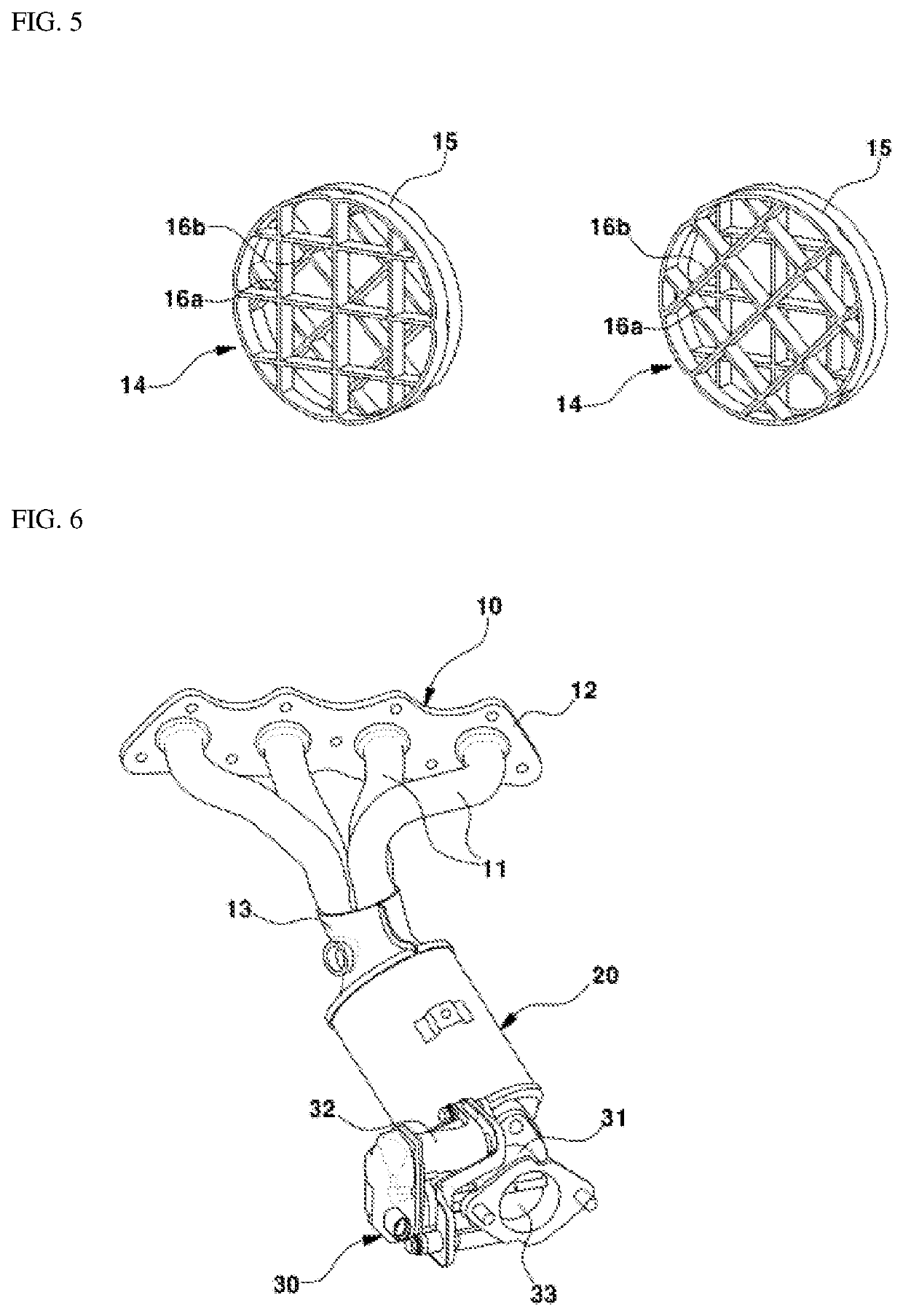
Benefits of technology

[0011]The present disclosure has been made in an effort to solve the above-described problems associated with prior art. In an aspect, the present disclosure provides a vehicle exhaust system capable of further improving a uniformity index (UI) of exhaust gas discharged through an exhaust manifold.
[0012]In an exemplary embodiment, a vehicle exhaust system may include an exhaust manifold configured to collect and transfer exhaust gas discharged from each cylinder of an engine, a catalytic purifier connected to an outlet of the exhaust manifold to reduce harmful substances in the exhaust gas flowing from the exhaust manifold, and a mesh member disposed between the exhaust manifold and the catalytic purifier to allow the exhaust gas to pass therethrough and having partition walls arranged to intersect longitudinally and transversely on an inner passage cross-section through which the exhaust gas passes. The partition walls of the mesh member may cause flow resistance while colliding with the exhaust gas to induce the exhaust gas to uniformly flow into a catalyst of the catalytic purifier.
[0016]The controller may be configured to output a control signal for operating the back-pressure regulation valve to be closed to a predetermined amount of opening of the valve in a catalyst heating (CH) section for catalyst warm-up during cold start of the engine. The controller may also be configured to operate the back-pressure regulation valve to be opened by increasing the amount of opening of the valve with the engine started after completion of the catalyst heating section.

Problems solved by technology

In addition, combustion gas is inevitably produced during the combustion of fuel in the engine, and the combustion gas (exhaust gas) is discharged to the atmosphere through the exhaust system of the vehicle.
Meanwhile, there is a limit to improve the fluidity of exhaust gas due to the limitation of the structure and shape of the exhaust manifold, and a new technique is thus required to further improve the uniformity index.

Method used


Image

  • Vehicle exhaust system
  • Vehicle exhaust system
  • Vehicle exhaust system

Examples


Embodiment Construction

[0025]It is understood that the term “vehicle” or “vehicular” or other similar term as used herein is inclusive of motor vehicles in general such as passenger automobiles including sports utility vehicles (SUV), buses, trucks, various commercial vehicles, watercraft including a variety of boats and ships, aircraft, and the like, and includes hybrid vehicles, electric vehicles, plug-in hybrid electric vehicles, hydrogen-powered vehicles and other alternative fuel vehicles (e.g. fuels derived from resources other than petroleum). As referred to herein, a hybrid vehicle is a vehicle that has two or more sources of power, for example both gasoline-powered and electric-powered vehicles.

[0026]Although exemplary embodiment is described as using a plurality of units to perform the exemplary process, it is understood that the exemplary processes may also be performed by one or plurality of modules. Additionally, it is understood that the term controller / control unit refers to a hardware devi...


PUM

PropertyMeasurementUnit
angleaaaaaaaaaa
timeaaaaaaaaaa
flow resistanceaaaaaaaaaa

Abstract

A vehicle exhaust system is provided to improve a uniformity index (UI) of exhaust gas discharged through an exhaust manifold. The system includes an exhaust manifold for collecting and transferring exhaust gas discharged from each cylinder of an engine and a catalytic purifier connected to an outlet of the exhaust manifold to reduce harmful substances in the exhaust gas flowing from the exhaust manifold. A mesh member is disposed between the exhaust manifold and the catalytic purifier to allow the exhaust gas to pass therethrough. The mesh member includes partition walls arranged to intersect longitudinally and transversely on an inner passage cross-section through which the exhaust gas passes. The partition walls cause flow resistance while colliding with the exhaust gas to induce the exhaust gas to uniformly flow into a catalyst of the catalytic purifier.

Description

CROSS-REFERENCE TO RELATED APPLICATION[0001]This application claims under 35 U.S.C. § 119(a) the benefit of priority to Korean Patent Application No. 10-2019-0051354 filed on May 2, 2019, the entire contents of which are incorporated herein by reference.BACKGROUND(a) Technical Field[0002]The present disclosure relates to a vehicle exhaust system, and more particularly, to a vehicle exhaust system that further improves a uniformity index of exhaust gas discharged through an exhaust manifold from a cylinder of a vehicle engine.(b) Background Art[0003]In general, a vehicle generates power necessary for driving by burning fuel in an engine. In addition, combustion gas is inevitably produced during the combustion of fuel in the engine, and the combustion gas (exhaust gas) is discharged to the atmosphere through the exhaust system of the vehicle.[0004]In recent years, as interest in the environment has increased, research and technology development for reducing the harmful substances cont...

Claims


Application Information

Patent Timeline
Patent Type & Authority Patents(United States)
IPC IPC(8): F01N3/10F01N3/28F01N9/00F01N3/20F01N13/10B01F23/10
CPCF01N3/2892F01N3/2006F01N9/00F01N13/10F01N13/00F01N3/00F02D9/04F02D9/10F01N2240/20F01N2260/06F01N2260/08F01N13/1872F01N3/10Y02A50/20F01N2410/14F01N2410/06
Inventor PARK, JUNG JOO
Owner HYUNDAI MOTOR CO LTD
Learn More