Integrated driving module

a driving module and integrated technology, applied in the field of driving modules, can solve the problems of inability to fully integrate, high manufacturing cost of the power converter, and inability to operate, so as to avoid the potential noise interference problem, reduce manufacturing cost, and simplify the overall design of the power supply.

Active Publication Date: 2021-03-16
ACBEL POLYTECH INC
View PDF1 Cites 4 Cited by
  • Summary
  • Abstract
  • Description
  • Claims
  • Application Information

AI Technical Summary

Benefits of technology

The present invention provides an integrated driving module that simplifies the circuit design, reduces manufacturing costs, and avoids potential noise interference. The module includes an oscillator, PWM unit, soft start controller, and drivers. The PWM unit generates two driving control signals with a 180-degree difference in phase, while the soft start controller ensures a smooth startup. The drivers receive the driving control signals and generate the output signals. This design eliminates the need for an extra circuit and input ports for the PWM signals, simplifies the overall design, and reduces manufacturing costs.

Problems solved by technology

Conventionally, bridge diodes are implemented in power factor correction (PFC) circuits for rectification, causing inevitable power loss.
Since the extra circuit is usually a weak point that is vulnerable to noises, it may lead to deformation of the control signals of the switch drivers and cause malfunction of the switch.
Furthermore, with the requirement of the extra output ports on the DSP, a low grade DSP chip is not an option and a high end DSP is needed, causing higher manufacturing cost of the power converter.

Method used


Image

  • Integrated driving module
  • Integrated driving module
  • Integrated driving module

Examples


second embodiment

[0027]Also with reference to FIG. 7, in the present invention, the integrated driving module 10 further includes a control end CTRL. The control end CTRL is connected to the oscillator OSC and the dead time generator DTG of the PWM unit PWM. The control end CTRL is for receiving a control signal from an external circuit. The oscillator OSC controls the frequency of the oscillating signal according to the control signal, and the dead time generator DTG also controls the delaying time according to the control signal.

[0028]The control signal received from the control end CTRL may be a digital signal; namely, the control signal is either a high-voltage signal or a low-voltage signal. When the control signal is a high-voltage signal, the frequency of the oscillating signal is a first frequency, and the delaying time of the dead time generator DTG is a first delaying time. When the control signal is a low-voltage signal, the frequency of the oscillating signal is a second frequency, and t...

third embodiment

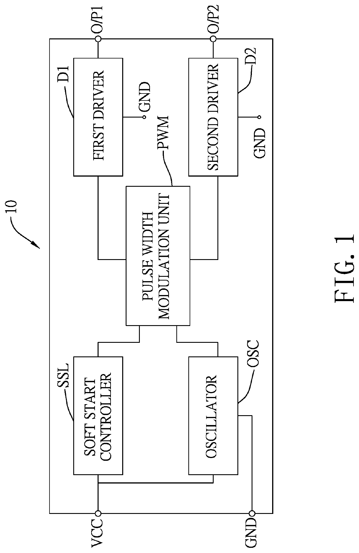
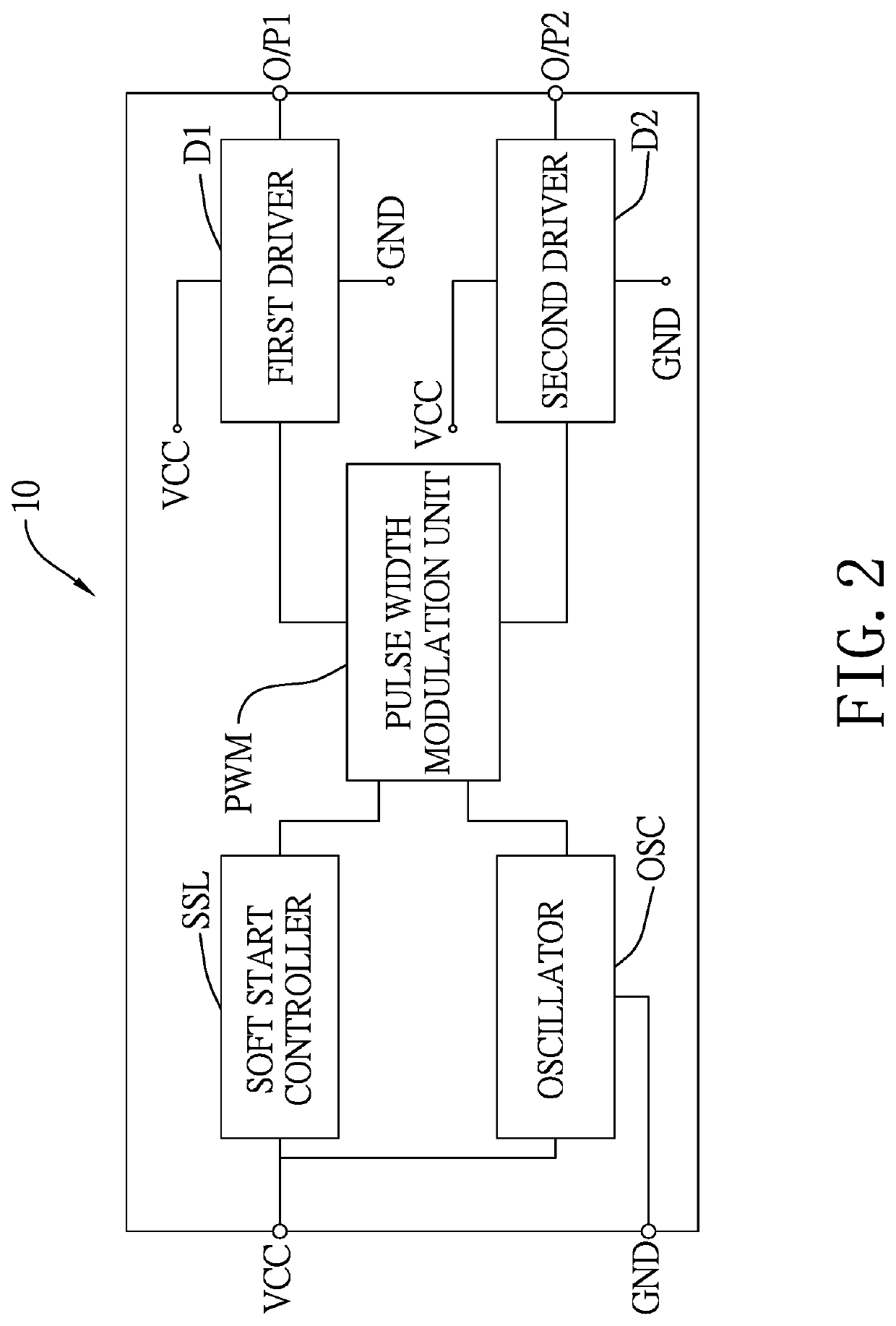
[0030]With reference to FIG. 8, in the present invention, the oscillator OSC is connected to the soft start controller SSL. When the soft start controller SSL receives the input voltage from the voltage input end VCC or the stabilized voltage from the low dropout regulator, the soft start controller SSL outputs the soft start control signal to the oscillator OSC to trigger the generation of the oscillating signal.

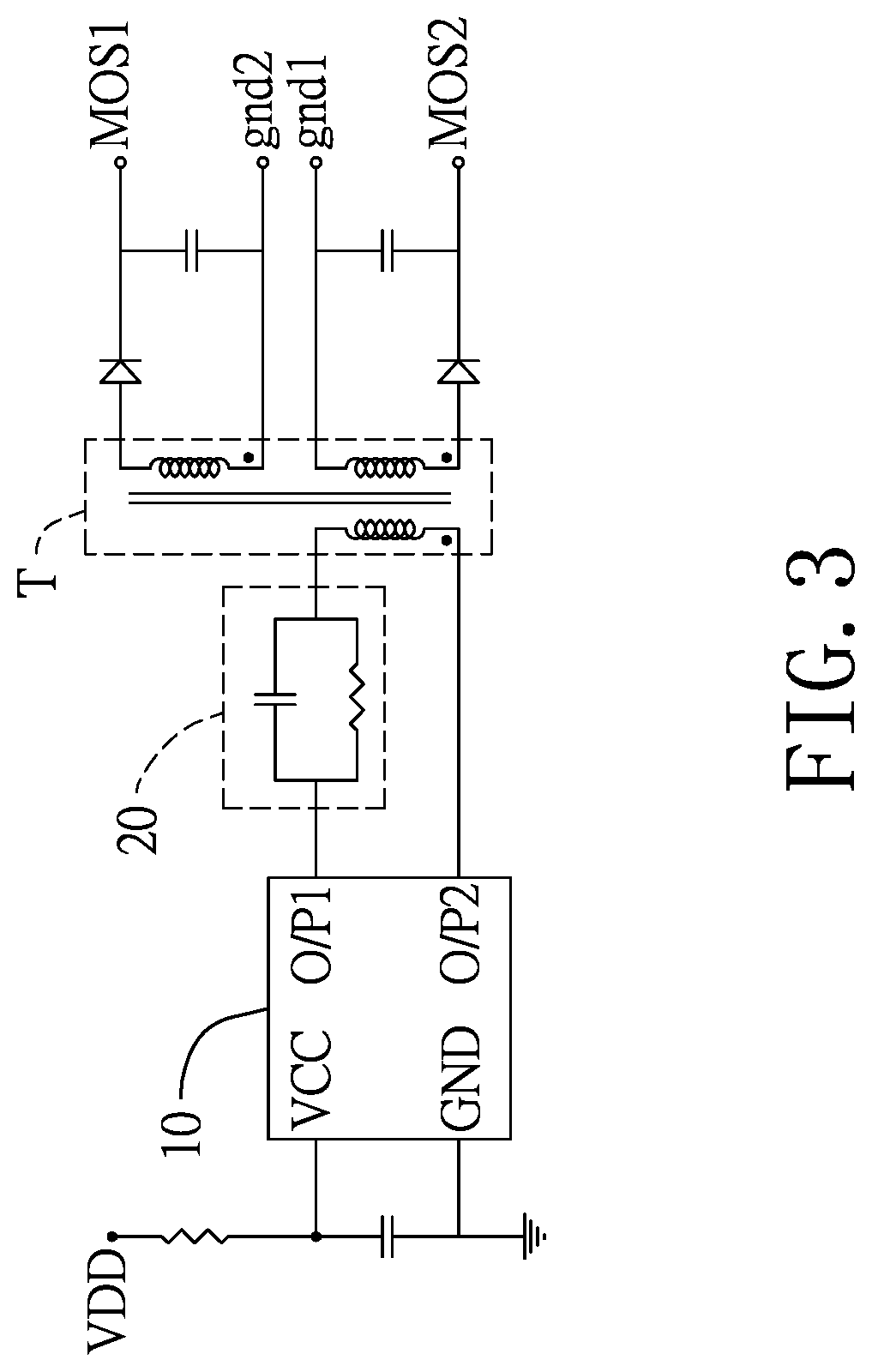
[0031]In conclusion, the integrated driving module 10 of the present invention requires at most five connecting ends, including the control end CTRL, to provide the two anti-phase driving output signals that are needed to synthesize an AC signal at the primary side of the transformer T. Therefore, there is no need to design extra layout and I / O ports from the separate control board. Furthermore, with the control signal received from the control end CTRL, the frequency and delaying time of the first driving output signal and the second driving output signal are easily regula...


PUM


Abstract

An integrated driving module includes an oscillator, a PWM unit, a soft start controller, a first driver, and a second driver. The oscillator is connected to a voltage input end and generates an oscillating signal. The PWM unit receives the oscillating signal and generates a first driving control signal and a second driving control signal that are respectively anti-phased. The first driver outputs a first driving output signal to a first output end according to the first driving control signal. The second driver outputs the second driving output signal to a second output end according to the second driving control signal. The integrated driving module only has four connection ends for external connection to provide the two anti-phase driving output signals, such that the circuit design and connection of the primary side of the transformer is greatly simplified. The design limitation and manufacturing cost can be both lowered.

Description

CROSS-REFERENCE TO RELATED APPLICATIONS[0001]This application claims the priority benefit of TW application serial No. 109102545, filed on Jan. 22, 2020. The entirety of the above-mentioned patent application is hereby incorporated by reference herein and made a part of the specification.BACKGROUND OF THE INVENTION1. Field of the Invention[0002]The present invention is related to a driving module, particularly related to an integrated driving module for generating galvanic isolated power.2. Description of the Related Art[0003]The efficiency of power supply devices is being improved in response to market demands. Conventionally, bridge diodes are implemented in power factor correction (PFC) circuits for rectification, causing inevitable power loss. Therefore, a PFC circuit with a non-bridge rectifier is the preferred choice nowadays. With reference to FIG. 9A, in a PFC circuit with a non-bridge rectifier, a Totem Pole circuit is implemented to improve the efficiency. The Totem Pole c...

Claims


Application Information

Patent Timeline
Patent Type & Authority Patents(United States)
IPC IPC(8): H03K17/16H03K17/691H02M1/42H03K3/356H03K7/08H02M1/38
CPCH03K17/162H02M1/38H02M1/4233H03K3/356182H03K7/08H03K17/691H02M1/08H02M1/36H03K5/1565H03K17/163
Inventor CHIU, JUI-YANGYEH, CHIA-AN
Owner ACBEL POLYTECH INC
Why Eureka
Try Eureka