
System and method for operating a vehicle in a low transmission range

a transmission range and low-range technology, applied in mechanical equipment, external condition input parameters, transportation and packaging, etc., can solve the problems of insufficiently high driveline noise and vibration, and the disturbance of downshift driveline torque, so as to increase the propulsive torque, generate a substantial amount of driveline noise and vibration, and increase the level of driveline braking

Active Publication Date: 2021-03-23
FORD GLOBAL TECH LLC
View PDF9 Cites 0 Cited by
  • Summary
  • Abstract
  • Description
  • Claims
  • Application Information

AI Technical Summary

Benefits of technology

[0002]A vehicle may include a transmission that may be put into a low gear range. The low gear range may provide higher levels of driveline braking during conditions where driver demand torque is low. The low gear range may also increase transmission output shaft speeds at which transmission gears are upshifted so that transmission gears may be held at engine speeds where engine torque production is greatest, thereby increasing the propulsive torque that may be delivered to a vehicle's wheels. If a human or autonomous driver engages the transmission in a low range while driver demand torque is low, the transmission output shaft speed at which the transmission is downshifted from a higher gear to a lower gear may be sufficiently high to generate a substantial amount of driveline noise and vibration. Further, the downshift may generate a larger driveline torque disturbance when the transmission is engaged in a low range since torque converter impeller speed may be higher during downshifting and since it may be more difficult to control torque transfer through gear clutches at higher driveline speeds. Therefore, it may be desirable to provide a way of operating a transmission in a low range with lower noise and vibration levels while still providing desirable levels of driveline braking.
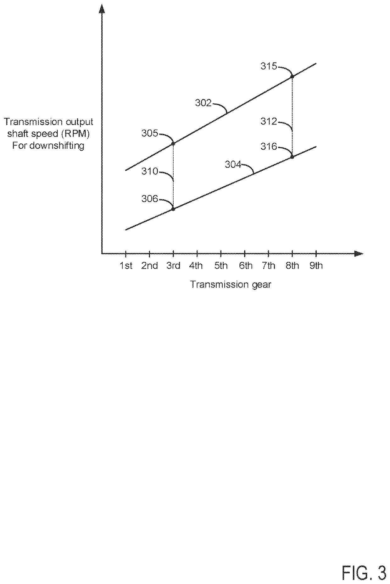
[0004]By adjusting an engagement speed of a transmission gear responsive to a braking torque request, it may be possible to provide the technical result of operating a driveline at a lower noise level, at least during some conditions. In particular, an engagement speed of a transmission gear may be lowered when a braking torque request is low so that driveline noise may be reduced when operating the transmission in a low range. Lower transmission gear engagement speeds may reduce driveline noise via lowering engine noise and electric machine noise. Even though the driveline noise and vibration may be reduced, the driveline may still provide desirable levels of braking when lower levels of braking are requested. However, if higher levels of driveline braking are requested, then the transmission gear engagement speed may be increased so that the requested braking level may be provided. In this way, driveline noise and vibration may be reduced while the driveline provides a desirable level of braking.
[0005]The present description may provide several advantages. In particular, the approach may reduce driveline noise while operating a transmission in a low range. Further, the approach may provide desirable levels of braking while operating the transmission in the low range. Further still, the approach may provide compensation for vehicle mass, requested braking, and road grade so that driveline noise and vibration may be controlled while providing desired levels of driveline braking.

Problems solved by technology

If a human or autonomous driver engages the transmission in a low range while driver demand torque is low, the transmission output shaft speed at which the transmission is downshifted from a higher gear to a lower gear may be sufficiently high to generate a substantial amount of driveline noise and vibration.
Further, the downshift may generate a larger driveline torque disturbance when the transmission is engaged in a low range since torque converter impeller speed may be higher during downshifting and since it may be more difficult to control torque transfer through gear clutches at higher driveline speeds.

Method used


Image

  • System and method for operating a vehicle in a low transmission range
  • System and method for operating a vehicle in a low transmission range
  • System and method for operating a vehicle in a low transmission range

Examples


Embodiment Construction

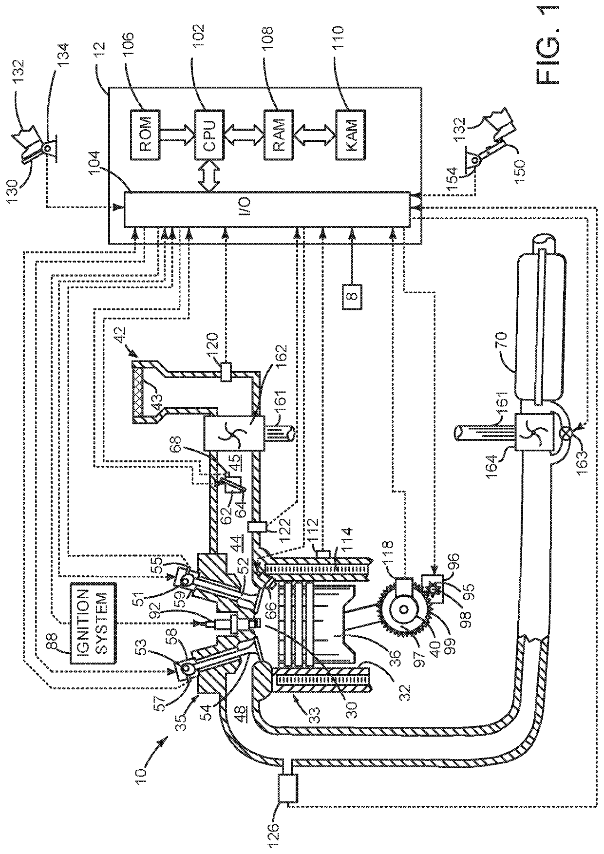
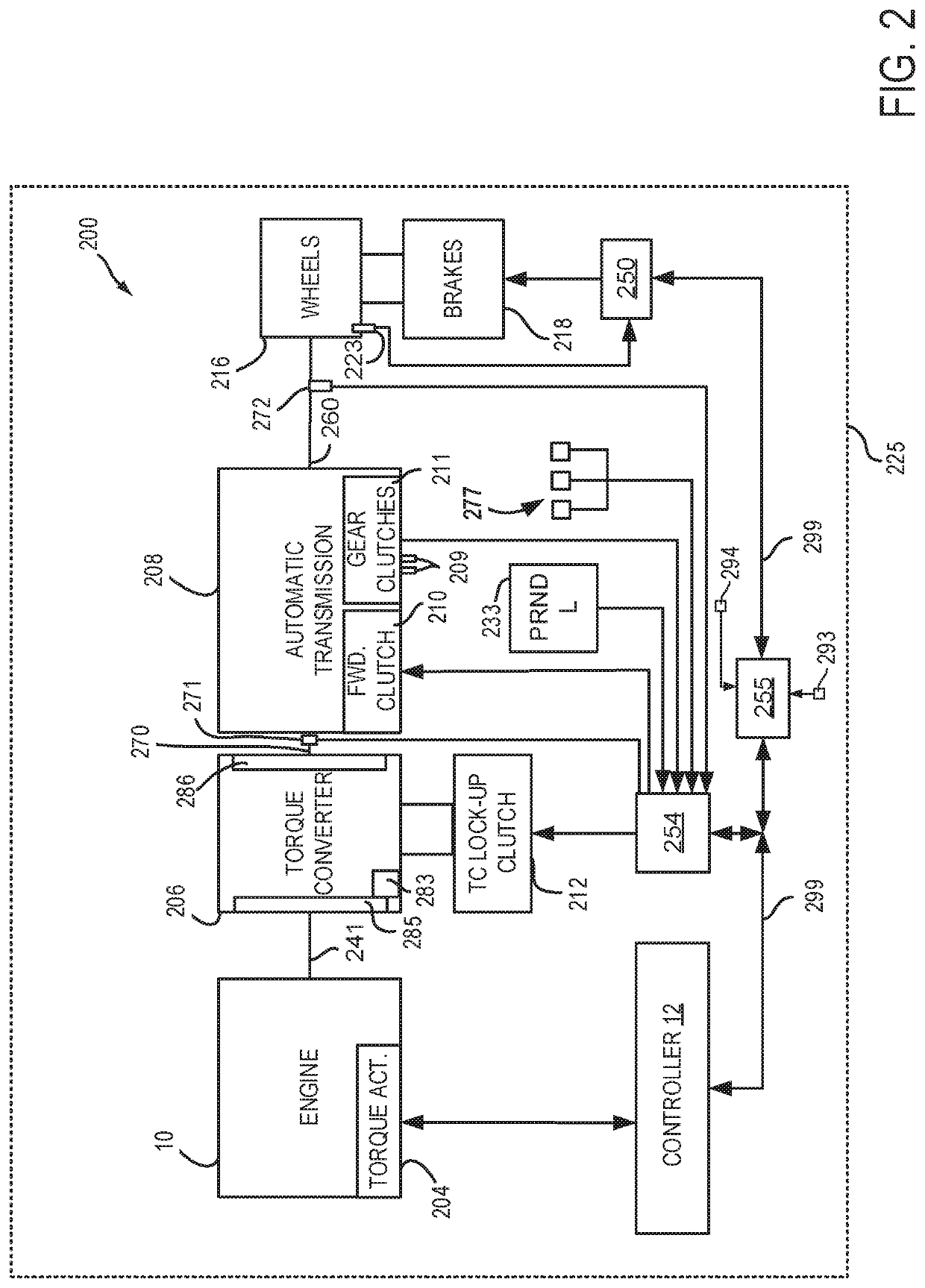
[0014]The present description is related to controlling a transmission of a driveline. The driveline may include an internal combustion engine as shown in FIG. 1. The internal combustion engine may be included in a driveline or powertrain of a vehicle as shown in FIG. 2. Gears of the transmission may be engaged during gear downshifts according to higher and lower engagement speeds as shown in FIG. 3. Several prophetic transmission downshifts are shown in FIG. 4. Finally, a method for shifting a transmission is shown in FIG. 5.

[0015]Referring to FIG. 1, internal combustion engine 10, comprising a plurality of cylinders, one cylinder of which is shown in FIG. 1, is controlled by electronic engine controller 12. Engine 10 is comprised of cylinder head 35 and block 33, which include combustion chamber 30 and cylinder walls 32. Piston 36 is positioned therein and reciprocates via a connection to crankshaft 40. Flywheel 97 and ring gear 99 are coupled to crankshaft 40. Optional starter 96...


PUM


Abstract

Systems and methods for operating a driveline that includes a step ratio transmission or a continuously variable transmission (CVT) that may be operated in a step ratio mode are disclosed. In one example, engagement speeds for transmission gears are adjusted as a function of vehicle mass, road grade, and requested braking torque.

Description

FIELD[0001]The present description relates to systems and method for operating a transmission in a low range where driveline braking may be increased. The system and methods may be suitable for powertrains that only include an internal combustion engines as a torque source and powertrains that include an internal combustion engine and an electric machine as torque sources.BACKGROUND AND SUMMARY[0002]A vehicle may include a transmission that may be put into a low gear range. The low gear range may provide higher levels of driveline braking during conditions where driver demand torque is low. The low gear range may also increase transmission output shaft speeds at which transmission gears are upshifted so that transmission gears may be held at engine speeds where engine torque production is greatest, thereby increasing the propulsive torque that may be delivered to a vehicle's wheels. If a human or autonomous driver engages the transmission in a low range while driver demand torque is...

Claims


Application Information

Patent Timeline
Patent Type & Authority Patents(United States)
IPC IPC(8): B60W30/19B60W50/08B60W20/10B60K6/547B60W40/13B60W40/105
CPCB60W50/082B60K6/547B60W20/10B60W30/19B60W40/105B60W40/13B60W10/101B60W40/00B60W40/076B60W2510/18B60W2710/1005B60W2710/1038B60W2552/15F16H59/52F16H61/0213F16H61/21F16H2059/186F16H2059/663F16H2061/0237
Inventor HILL, THADDEUSDIAKIW, MARKIAN OLEHHOLMES, JEFFREY RANDOLPHNICKERSON, KURT HOWARD
Owner FORD GLOBAL TECH LLC
Learn More