Microwave resonator readout of an ensemble solid state spin sensor

a solid state spin sensor and microwave resonator technology, applied in the direction of magnetic property measurement, using reradiation, instruments, etc., can solve the problems of low readout fidelities (f1) of fluorescence-based spin-center-defect measurement, high cost, and high cost, so as to reduce the input microwave radiation and enhance the interaction of spin center defects

Active Publication Date: 2021-03-30
MASSACHUSETTS INST OF TECH
View PDF20 Cites 1 Cited by
  • Summary
  • Abstract
  • Description
  • Claims
  • Application Information

AI Technical Summary

Benefits of technology

[0011]An inventive sensor system may include a microwave resonator, a solid-state host electromagnetically coupled to the microwave resonator and containing spin defect centers, a microwave radiation source in electromagnetic communication with the microwave resonator and the spin defect centers, and a detector in electromagnetic communication with the microwave resonator and the spin defect centers. In operation, the microwave radiation source applies microwave radiation to the microwave resonator and the spin defect centers. The microwave resonator enhances the interaction between the microwave radiation and the spin defect centers. And the detector measures an amplitude and / or a phase of the microwave radiation exiting the microwave resonator after interacting with the spin defect centers.

Problems solved by technology

Unfortunately, reading out a solid-state spin sensor using fluorescent light described above has a fundamental drawback: determining the quantum states of the spin center defects using the fluorescent light can be highly inefficient.
Readout fidelity also affects measurement time.
This makes the low readout fidelities (F<<1) of fluorescence-based spin-center-defect measurements highly disadvantageous for measuring transient physical quantities with relatively high SNR.

Method used


Image

  • Microwave resonator readout of an ensemble solid state spin sensor
  • Microwave resonator readout of an ensemble solid state spin sensor
  • Microwave resonator readout of an ensemble solid state spin sensor

Examples


Embodiment Construction

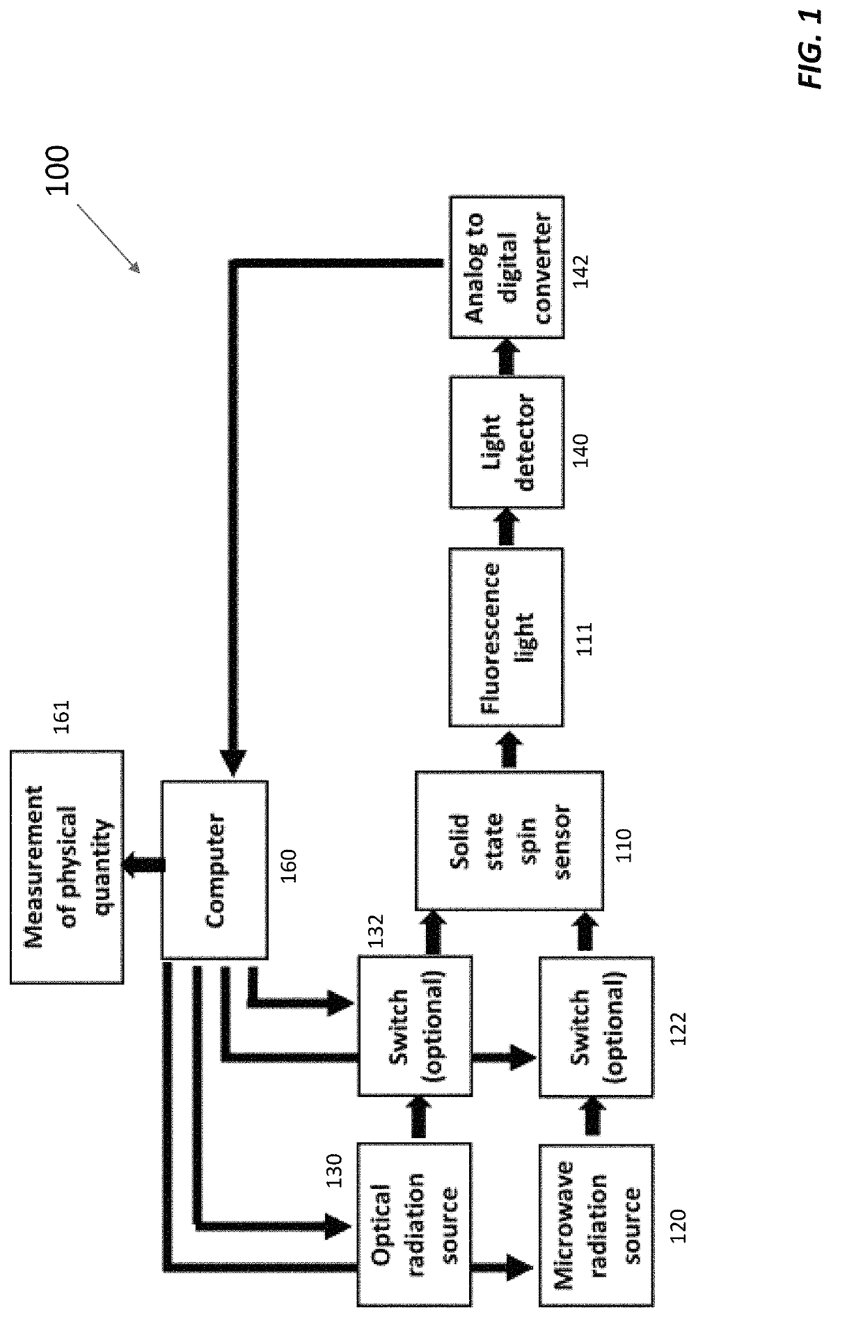
"d_n">[0036]An inventive solid-state spin sensor system encodes a physical quantity in the phase or amplitude of microwave radiation that has interacted with spin center defects within a solid-state spin sensor. Encoding the physical quantity in the phase and / or amplitude of microwave radiation, instead of optical radiation, greatly enhances the readout fidelity of and sensitivity of bulk-ensemble solid state spin sensors to physical parameters of interest and, as an all-electrical readout mechanism, may be preferable to all-optical readout mechanisms. The solid-state spin sensor system is also more compatible with standard semiconductor process manufacturing than devices employing all-optical readout mechanisms. And thanks to microwave resonator readout, an inventive solid-state spin sensor system can work well with many more types of spin defects, including almost any paramagnetic spin defect, than are compatible with optical readout.

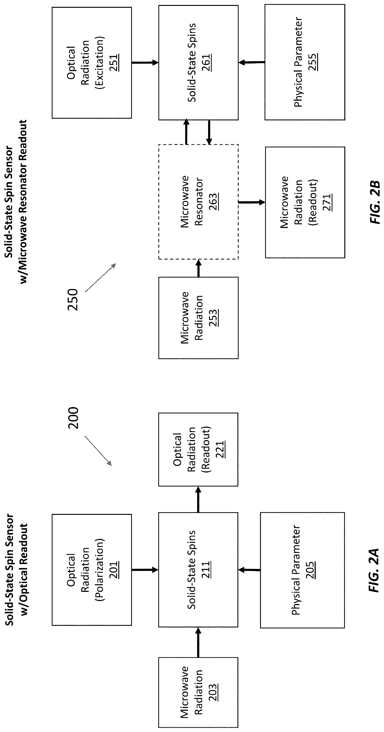
Differences Between Optical Readout and Microwa...


PUM


Abstract

Microwave resonator readout of the cavity-spin interaction between a spin defect center ensemble and a microwave resonator yields fidelities that are orders of magnitude higher than is possible with optical readouts. In microwave resonator readout, microwave photons probe a microwave resonator coupled to a spin defect center ensemble subjected to a physical parameter to be measured. The physical parameter shifts the spin defect centers' resonances, which in turn change the dispersion and / or absorption of the microwave resonator. The microwave photons probe these dispersion and / or absorption changes, yielding a measurement with higher visibility, lower shot noise, better sensitivity, and higher signal-to-noise ratio than a comparable fluorescence measurement. In addition, microwave resonator readout enables coherent averaging of spin defect center ensembles and is compatible with spin systems other than nitrogen vacancies in diamond.

Description

CROSS-REFERENCE TO RELATED APPLICATION(S)[0001]This application claims the priority benefit, under 35 U.S.C. 119(e), of U.S. Application No. 62 / 723,113, filed on Aug. 27, 2018, which is incorporated herein by reference in its entirety.GOVERNMENT SUPPORT[0002]This invention was made with Government support under Grant No. FA8702-15-D-0001 awarded by the U.S. Air Force. The Government has certain rights in the invention.BACKGROUND[0003]Solid-state spin sensors employ spin center defects, including color center defects, in a solid-state host to measure one or more physical parameters or quantities, such as magnetic field, electric field, temperature, pressure, or the presence of an atomic, molecular, or other hadronic species. The spin center defects are point-like defects inside the solid-state host, such as nitrogen vacancies (NVs) in diamond, that sense the physical quantity. Their quantum spin states can be manipulated by optical excitation and microwave radiation, making the quant...

Claims


Application Information

Patent Timeline
Patent Type & Authority Patents(United States)
IPC IPC(8): G01V3/00G01R33/12G01R33/32G01R33/26
CPCG01R33/1284G01R33/26G01R33/323G01R33/032G01N24/006G01R33/0017G01R33/60G01N24/10G01R33/345
Inventor BARRY, JOHN F.EISENACH, ERIK R.O'KEEFFE, MICHAEL F.MAJUMDER, JONAH A.PHAM, LINH M.CHUANG, ISAACTHOMPSON, ERIK M.PANUSKI, CHRISTOPHER LOUISZHANG, XINGYUBRAJE, DANIELLE A.
Owner MASSACHUSETTS INST OF TECH
Why Eureka
Try Eureka