Rotary tool

a technology of rotating tools and cutting tools, which is applied in the direction of milling cutters, turning machine accessories, manufacturing tools, etc., can solve the problems of high-precision cutting of large inside diameters, and achieve the effect of excellent handling and low cos

Active Publication Date: 2021-04-06
GUEHRING OHG
View PDF20 Cites 0 Cited by
  • Summary
  • Abstract
  • Description
  • Claims
  • Application Information

AI Technical Summary

Benefits of technology

[0004]Therefore, it is the object of the invention to provide a rotary tool especially for the cutting production of large-diameter boreholes which excels by excellent handling so that during machining the observation of the dimensional stability of the borehole is safeguarded. Said rotary tool is moreover intended to be manufactured at low cost and yet to meet the requirements of high mechanical load capacity.
[0005]According to the invention, the object is achieved in a generic rotary tool by the fact that the support structure widens / expands in an umbrella-type or lightshade-type or jaw-type / jaw-like manner starting from a coupling portion adjacent to the chucking portion and is radially stiffened by a stiffening structure. The umbrella-type or jaw-type widening of the support structure, on the one hand, helps to ensure proper torque transmission from the chucking portion to the support structure and, on the other hand, helps to design the rotary tool in light-weight construction as well as to manufacture it at low cost and in a simple manner. The provided rotary tool thus is designed in such a manner that the material required for its construction is as small as possible. The “principal function” of machining is adopted by the support structure, wherein starting from the chucking portion the torque and, resp., the force is introduced to the support structure, whereas the stiffening structure fulfils a “secondary function” and stiffens the support structure in the radial direction so that the at least one cutting edge is supported in the radial direction at the outer circumference of the rotary tool. By the umbrella-type or jaw-type widening, an appropriately high torsion resistance moment of the support structure and thus of the rotary tool can be formed due to a large distance of the support structure from an axis of rotation of the rotary tool. The umbrella-type widening results in a radially inner area or volume of the rotary tool which is located outside the torque transmission of the rotary tool, as afore-described. Said “freely available” volume located outside the force transmission enables a stiffening structure to be integrated in the rotary tool for stiffening the support structure in the radial direction, while the total weight of the tool is only insignificantly increased. Due to the resulting low weight of the rotary tool, the rotary tool can be handled by far better than it is known from the state of the art, even if it requires a considerable axial length. At the same time, dynamic unbalance loads and weight-related deflections of the rotary tool are reduced, thus resulting in a substantially increased machining accuracy.

Problems solved by technology

Especially by the fact that more and more electromotive drives or conventional gearings having a higher number of speeds are required, there is a more urgent problem of high-precision cutting large inside diameters such as the inside diameter of a stator housing of an electric motor.

Method used


Image

  • Rotary tool
  • Rotary tool
  • Rotary tool

Examples


Embodiment Construction

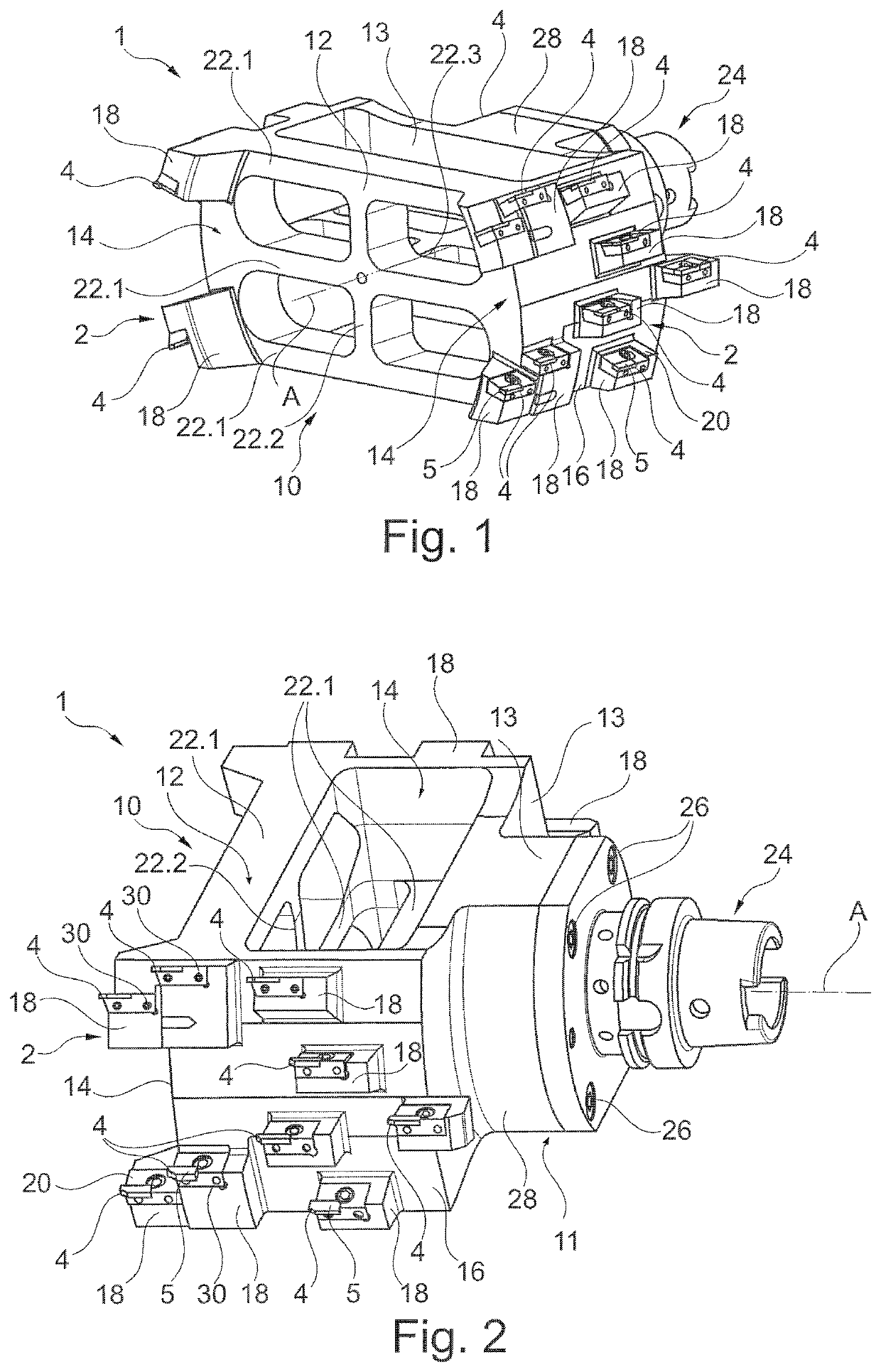
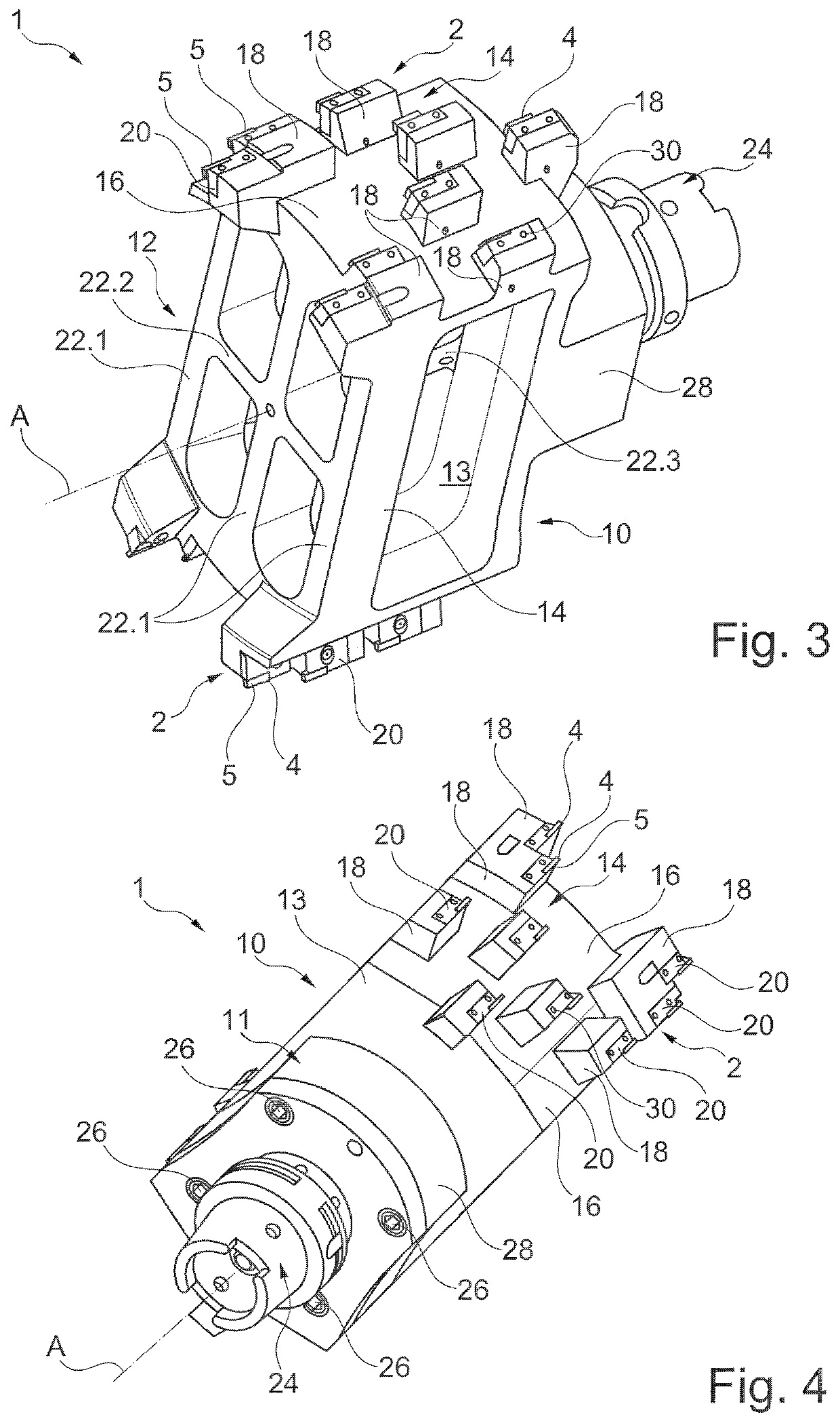
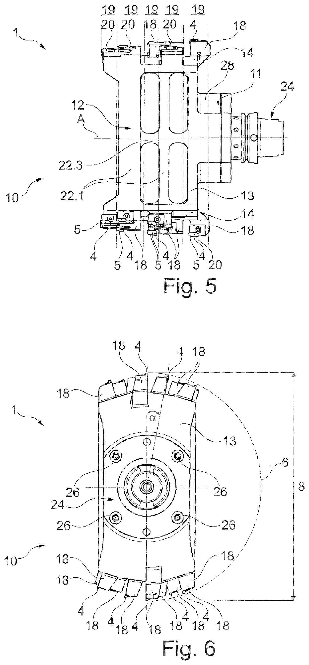
[0071]FIG. 1 to FIG. 4 illustrate in different perspective views a rotary tool 1 according to the invention of a preferred embodiment in the form of a stepped reamer. The rotationally driven rotary tool 1 is configured to be point-symmetric about an axis of rotation A and serves for high-precision machining of especially metallic components, components of plastics or components of fiber composite materials. For this purpose, at an outer circumference 2 of the rotary tool 1 cutting edges 4 are located which during rotation of the rotary tool 1 about the axis of rotation A remove chips of material from a workpiece to be machined (not shown). The cutting edges 4 are configured in the form of an edge in parallel to the axis of rotation A at a cutting member 5. During rotation about the axis of rotation A, each of radially outer points of the cutting edges 4 at the outer circumference 2 describes a circular cutting circle 6 having a related cutting circle diameter 8 (see the exemplary cu...


PUM


Abstract

The invention relates to a rotary tool (1; 101; 201) for cutting large inside diameters at the outer circumference (2) of which at least one cutting edge (4) is arranged, comprising a support structure (10; 110; 210) which indirectly or directly supports the at least one cutting edge (4), and comprising a chucking portion (24) for coupling to a tool holder, wherein the support structure (10; 110; 210) widens in an umbrella-type manner starting from a coupling portion (11) adjacent to the chucking portion (24) and is radially stiffened by a stiffening structure (12).

Description

TECHNICAL FIELD[0001]The invention relates to a rotary tool / rotating tool, for example in the form of a reamer or a stepped reamer, for cutting large inside / inner diameters, at the outer circumference of which at least one cutting edge is arranged, the rotary tool comprising a support structure which indirectly or directly supports the at least one cutting edge, and comprising a chucking portion for coupling to a tool holder. The chucking portion may take / have any shape, preferably such shape that it can be coupled to the respective spindle of a machine tool via common tool holders such as a hollow-shank taper holder (HSK taper).STATE OF THE ART[0002]Especially by the fact that more and more electromotive drives or conventional gearings having a higher number of speeds are required, there is a more urgent problem of high-precision cutting large inside diameters such as the inside diameter of a stator housing of an electric motor. The machining tools used here must be dimensionally s...

Claims


Application Information

Patent Timeline
Patent Type & Authority Patents(United States)
IPC IPC(8): B23D77/02B23C5/00B23D77/00B23C5/04B23D77/04
CPCB23D77/02B23C5/006B23C5/04B23D77/00B23D77/04B23D2277/02B23B27/16B23B29/03B23C2226/27
Inventor HAENLE, PETERBISCHOFF, THOMAS
Owner GUEHRING OHG
Why Eureka
Try Eureka