Foam core duct system protected by metal sleeves with integral flanges

a duct system and foam core technology, applied in the direction of ducting arrangements, lighting and heating apparatus, heating types, etc., can solve the problems of increasing the risk of moisture intrusion, and increasing the risk of duct body penetration, etc., to achieve cost-effective, high-durability, and easy and more cost-effective manufacturing

Active Publication Date: 2021-04-13
ALBERS MECHANICAL CONTRACTORS INC
View PDF23 Cites 7 Cited by
  • Summary
  • Abstract
  • Description
  • Claims
  • Application Information

AI Technical Summary

Benefits of technology

[0009]The present invention provides improved, foam-based duct systems that are more easily and more cost effectively manufactured than conventional foam-based duct systems. The foam-based duct systems of the present invention provide a cost effective, highly durable shell to provide foam-based duct systems with more durability and resistance to damage. This enhanced protection helps to improve service life and durability performance in exterior and interior applications as well as to reduce the risk of other damage during shipping, installation, and use. An improved flange system also is provided that is easier to install, provides an excellent thermal break, and is light in weight. The duct systems also are characterized by high strength, low weight, and energy efficiency.

Problems solved by technology

This system requires a considerable number of screws to assemble, with a corresponding large number of penetrations down into the duct bodies.
Not only does this involve substantial labor for installation, the numerous penetrations increase the risk of moisture intrusion and associated issues.
Conventional duct systems fabricated from foam panels unfortunately suffer from drawbacks.
One drawback is that the shell materials used on commercially available systems are easy to dent or otherwise damage.
The shell materials can suffer too easily from tears, dents, abrasions, and the like.
Additionally, some of the shell materials are not sufficiently stable or durable enough for outdoor applications where systems are exposed to sunlight, blowing debris, hail, ice, and other damaging, environment elements.
Some of the cladding strategies are quite expensive, making foam-based systems more expensive than conventional sheet metal systems.
The result is that these coupling structures penetrate deeply into the juncture between duct sections, allowing too much thermal or cooling losses.
The separate coupling structures also add expense and manufacturing complexity, where an installation error could ruin an entire duct section as damage to foam cores might not be easily or cost effectively repaired.
This approach for attaching coupling structures to the ends of duct sections can impose an increased risk of manufacturing yield losses.
The conventional coupling structures also are quite heavy, undermining the light weight advantage that otherwise is inherent in using a foam-based product.
The resultant flanges are strong, but still lightweight.
In some circumstances, this may cause undue amounts of condensation to occur inside a duct passage.
Conventional systems with this problem have taken extra measures to protect against this problem, which is time consuming to install as well as more expensive.

Method used


Image

  • Foam core duct system protected by metal sleeves with integral flanges
  • Foam core duct system protected by metal sleeves with integral flanges
  • Foam core duct system protected by metal sleeves with integral flanges

Examples


Embodiment Construction

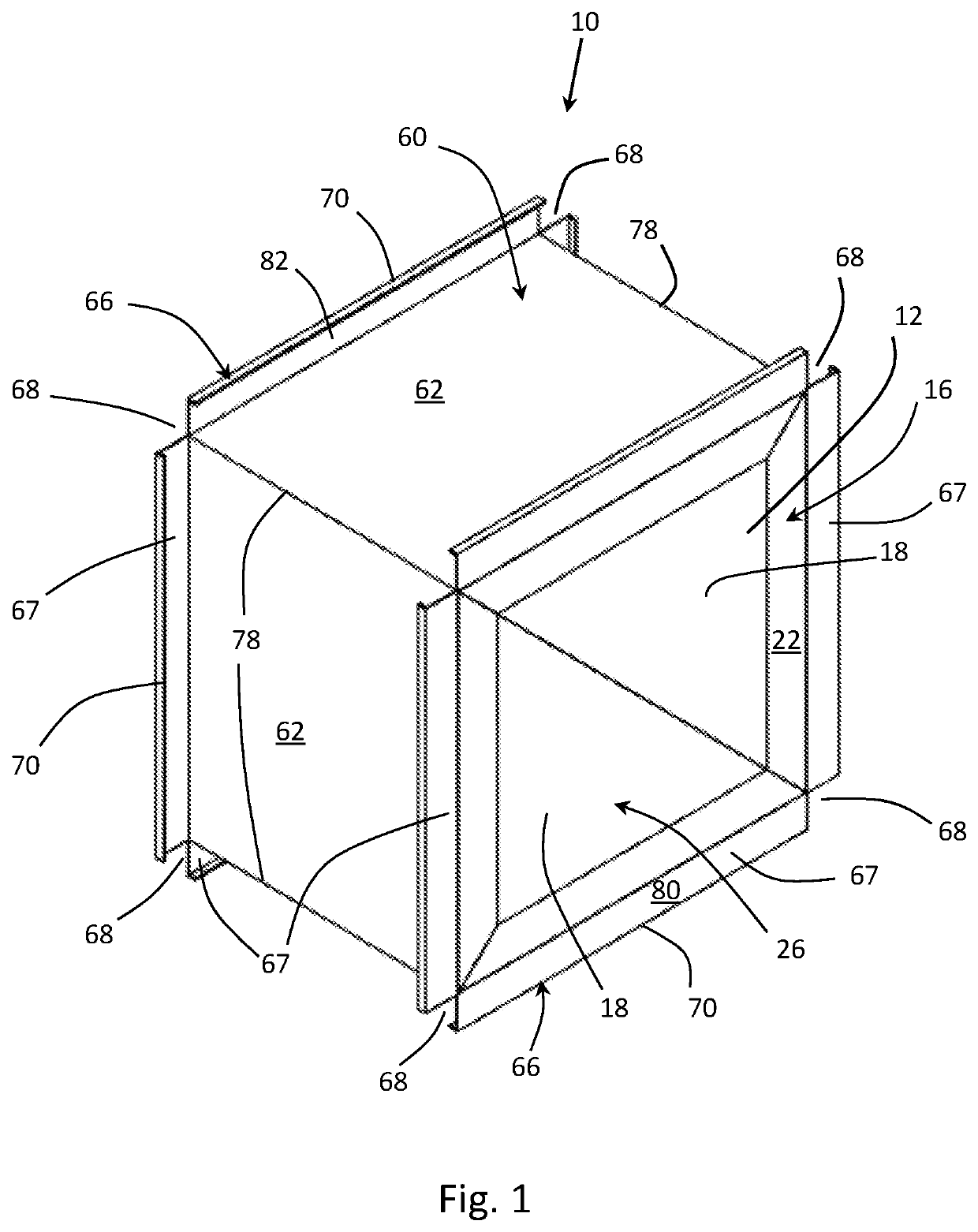
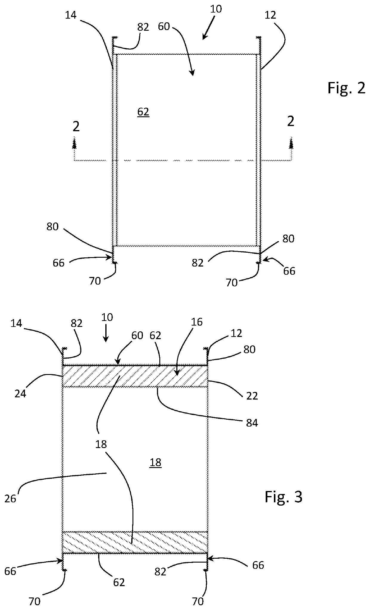
[0055]An exemplary embodiment of a duct section 10 of the present invention is shown in FIGS. 1 to 3. Duct section 10 generally extends from a first end 12 to a second end 14 and includes a foam body 16 and an external rigid sleeve 60. Foam body 16 includes side panels 18 defining a central duct 26 through which a fluid such as HVAC air flows when duct section 10 is installed as a component in an HVAC duct system. In many embodiments, side panels 18 are generally made from rigid foam panels having a thickness in the range from 0.5 inches to about 4 inches, preferably 1 inch to about 3 inches, more preferably about 1 inch to about 2 inches. The thickness of the side panels 18 provide foam body 16 with a first end face 22 and a second end face 24 that generally are co-extensive with first end 12 and second end 14. The thickness of the side panels 18 helps to provide duct section 10 with overall rigidity and strength while still allowing duct section 10 to be lightweight. The thickness...


PUM


Abstract

This application relates to a duct system, including a duct section that includes a foam body having a first end face and a second end face, where the foam body defines a duct passage extending from the first end face to the second end face, and a sleeve that directly or indirectly covers the foam body, the first sleeve including a plurality of side walls, where at least one side wall has an integral end portion that is folded back to define at least a portion of an integral, peripheral coupling flange around an end face of the foam body.

Description

CROSS-REFERENCE TO RELATED APPLICATIONS[0001]The present application claims priority to U.S. Provisional Patent Application No. 62 / 479,951 filed Mar. 31, 2017, the entire contents of which is incorporated herein by reference it its entirety for all purposes.FIELD OF THE INVENTION[0002]The present invention relates to duct system components for HVAC applications that are made from foam panels that are enclosed within protective shells. More particularly, the present invention relates to such duct components in which flanges at each end of a duct section are integral with the protective shell.BACKGROUND OF THE INVENTION[0003]Duct systems are used in the field of heating, ventilation, and air conditioning (HVAC) to manage the intake, distribution, treatment, and exhaust of air in land and sea-based residential, industrial, commercial, and government applications. HVAC technology is used for vehicles, marine vessels, aircraft, spacecraft, buildings, and the like. A main goal of HVAC tec...

Claims


Application Information

Patent Timeline
Patent Type & Authority Patents(United States)
IPC IPC(8): F24F13/02F16L23/14
CPCF24F13/0209F16L23/14F24F13/0245F24F13/0263F24F13/0281F16L9/003
Inventor ALBERS, CHARLES G.
Owner ALBERS MECHANICAL CONTRACTORS INC
Why Eureka
Try Eureka