Eureka AIR delivers breakthrough ideas for toughest innovation challenges, trusted by R&D personnel around the world.

Anti-surge speed control for two or more compressors

a compressor and speed control technology, applied in the direction of machines/engines, mechanical equipment, separation processes, etc., can solve the problems of compressor surge condition, compressor impeller damage, drive mechanism and components, compressor to move off the peak efficiency operating line and into a surge condition, etc., to achieve the effect of increasing or reducing the average speed of the compressor

Active Publication Date: 2021-04-27
PRAXAIR TECH INC
View PDF38 Cites 0 Cited by
  • Summary
  • Abstract
  • Description
  • Claims
  • Application Information

AI Technical Summary

Benefits of technology

[0020]Since the GSF is applied to adjust the speed of the compressors for every step in the cycle, it effectively reduces or increases the average speed of the compressors that are constantly varying in speed during the process. By using pressure measurements in the vessels of the apparatus as feedback to control the value of the GSF, the average amount of gas entering and leaving each vessel is varied continuously from one cycle to the next to ensure that the cyclic pressure trace achieved in the vacuum pressure swing process are within limits and stable across many cycles.
[0021]In some embodiments of the present invention, it may be advantageous to assign the same GSF associated with the speed of a given compressor to each vessel in the process. In this case, there will be one GSF for each compressor of the apparatus. In other embodiments, it may be more advantageous to use a different GSF associated with each compressor and vessel pair. For an example of a two-vessel pressure-swing process driven by two different compressors, there will be four different GSF in this case. The latter case is advantageous when the embodiments of the present invention are applied to the production of oxygen from air using a VPSA process, as there are often variations between the nitrogen capacity of the adsorbent from one vessel to another. Varying the speed of each machine-vessel pair across all steps of operation where they are fluidly connected, therefore, can ensure that the balance criterion is maintained for the process.
[0023]A controller is provided that is responsive to the parameter sensing means, the pressure transducers and steps of a repeating cycle conducted by the vacuum pressure swing adsorption apparatus. The controller has a control program that is programmed to calculate a pressure ratio of the pressures of the outlet to inlet of the centrifugal compressor. The control program also determines an optimal speed of the centrifugal compressor based on the pressure ratio and that lies along the peak efficiency operating line of the centrifugal compressor. A minimum allowable value of the parameter at which the centrifugal compressor is likely to enter surge conditions at the optimal speed is determined by the controller along with a feedback multiplier that when multiplied by the optimal speed will either increase the speed when the parameter is less than the minimum allowable value or will reduce the speed when the parameter is greater than or equal to the minimum allowable value. A total speed multiplier is set equal to the product of the feedback multiplier and global speed factor during the steps of the repeating cycle where the centrifugal compressor is at least likely to enter surge conditions, other than a pure evacuation step and an evacuation with product purge step thereof. The total speed multiplier is set equal to a mathematical product of the feedback multiplier, feed forward multiplier, and global speed factor during the pure evacuation step and the evacuation with product purge step, that will increase the speed such that centrifugal compressor is not likely to enter surge conditions. Global speed factors are determined from the previous highest adsorption pressure at the end of feed and the lowest desorption pressure end of the purge steps for each vessel in the apparatus, wherein the global speed factor will increase the speed over all steps for each compressor when the obtained highest adsorption pressure is too low and the obtained lowest desorption pressure is too high. An adjusted speed is calculated by multiplying the optimal speed by the total speed multiplier, which includes the effect of the global speed factor.

Problems solved by technology

There are, however, situations that can cause the compressor to move off the peak efficiency operating line and into a surge condition.
In a surge event, the head pressure developed by the compressor decreases, causing a reverse pressure gradient at the compressor discharge and a resulting backflow of gas.
This alternating flow pattern has been found to be an unstable condition that can result in serious damage to the compressor impeller, drive mechanism and components.
Additionally, during the evacuation and purge steps and particularly during the transition between the purge and evacuation steps, surge is likely to occur.
If this condition is not satisfied, the process can enter a state where it is not taking feed or producing product as designed, which disrupts the continuous production from the apparatus.
Additionally, for the operation of a vacuum pressure swing apparatus for the production of oxygen from air with variable-speed compressors, the pressure trace in the cycle steps is very strongly affected by the operation of the associated variable-speed compression equipment.
The consequence of deviation from the stable operation condition of a continuous, identical pressure variation cycle in each vessel can be damage to the compressors, including from surge events.

Method used


Image

  • Anti-surge speed control for two or more compressors
  • Anti-surge speed control for two or more compressors
  • Anti-surge speed control for two or more compressors

Examples


Embodiment Construction

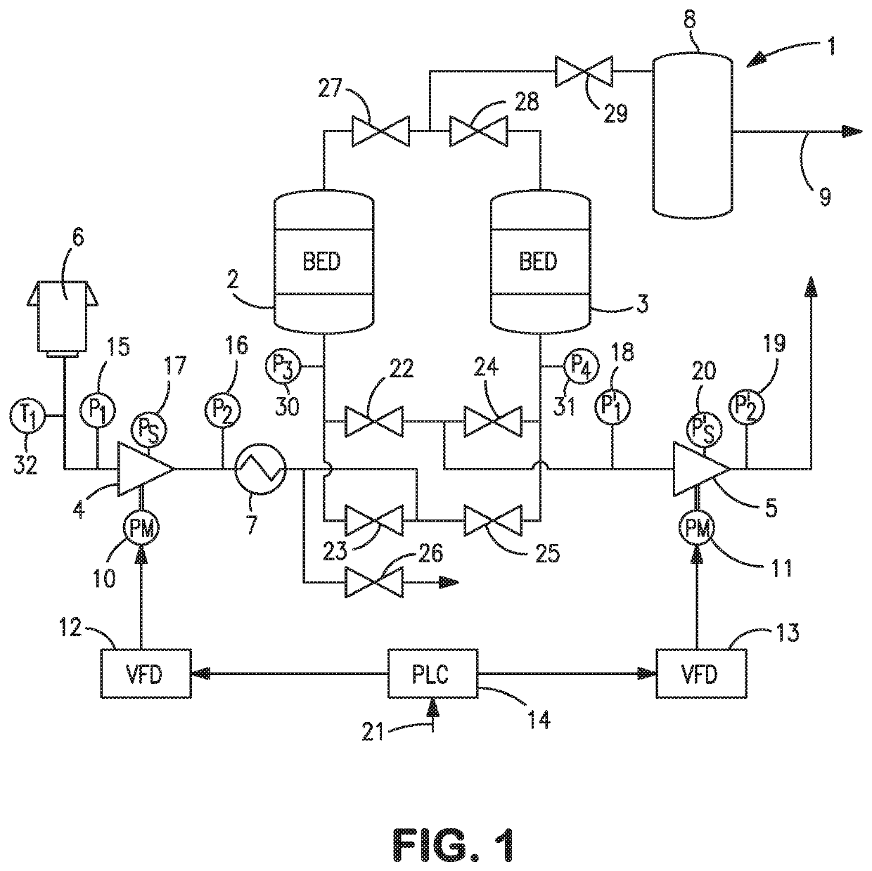
[0038]With reference to FIG. 1, a vacuum pressure swing adsorption apparatus 1 is illustrated that is designed to produce an oxygen product. Although vacuum pressure swing adsorption apparatus 1 is a two-bed design, it is understood that this is for purposes of illustration and the present invention would have equal applicability to a single or multiple bed design using a single or multiple compressors designed to pressurize and evacuate an adsorbent bed or beds. Furthermore, the present invention is equally applicable to vacuum pressure swing adsorption apparatus designed to produce other products such as carbon dioxide, nitrogen, hydrogen or helium. As such, the vacuum pressure swing adsorption apparatus 1 is shown and described herein for exemplary purposes only.

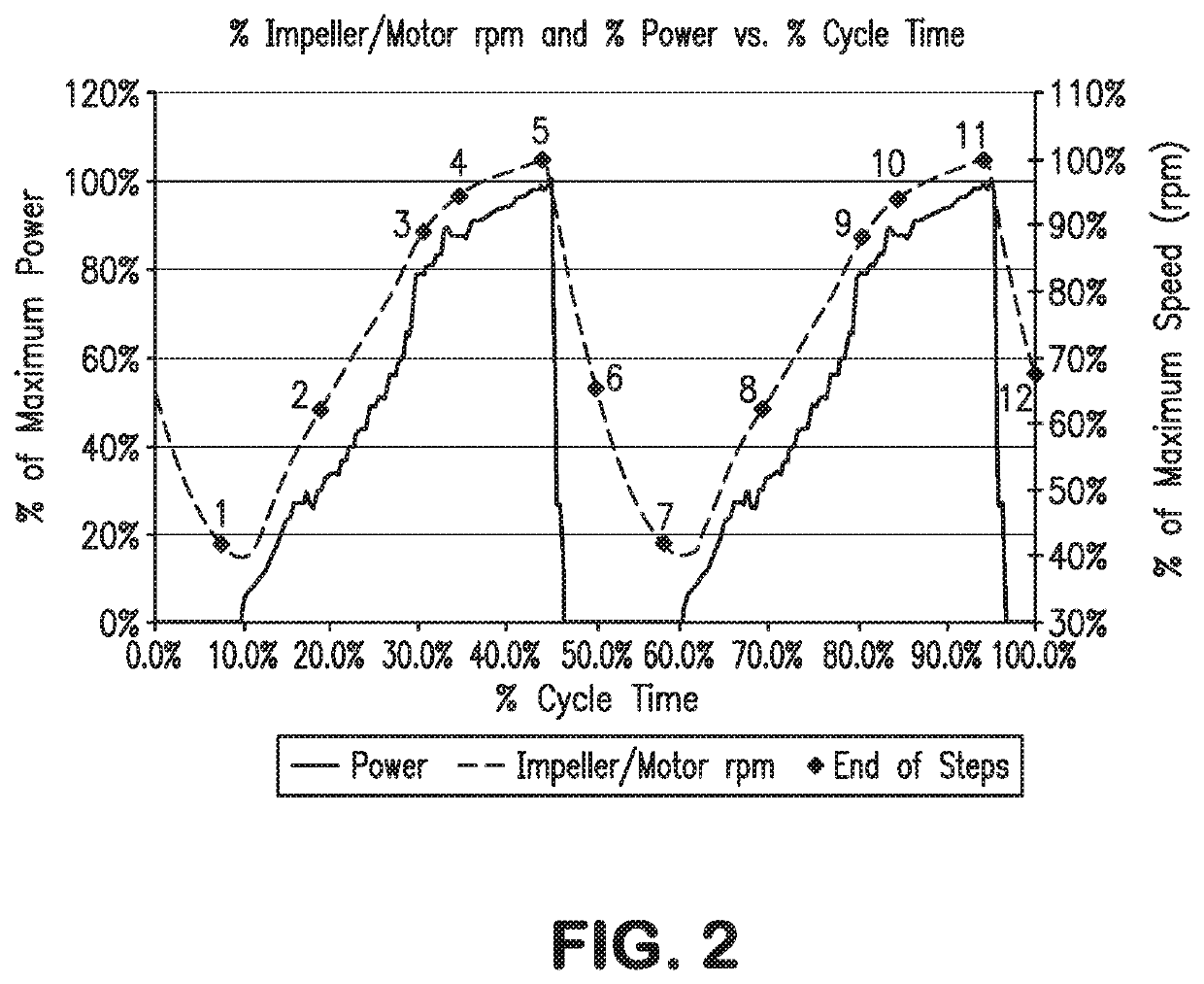
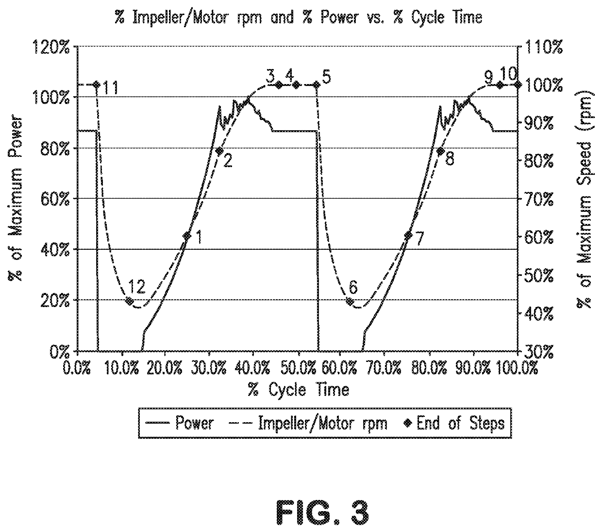
[0039]With reference to FIG. 1, an apparatus 1 is illustrated for conducting a vacuum pressure swing adsorption cycle in which two adsorbent beds 2 and 3 are subjected to a twelve step vacuum pressure swing adsorption cyc...


PUM


Abstract

The present invention relates to a method and control system to control the speed of centrifugal compressors operating within a vacuum pressure swing adsorption process to avoid an operation at which surge can occur and directly driven by an electric motor that is in turn controlled by a variable frequency drive, while subsequently operating the vacuum pressure swing process between set limits of highest adsorption and lowest desorption pressure. In accordance with present invention an optimal speed for operation of the compressor is determined at which the compressor will operate along a peak efficiency operating line of a compressor map thereof. This speed is adjusted by a feed back speed multiplier when the flow or other parameter referable to flow through the compressor is below a minimum and a feed forward multiplier during evacuation and evacuation with purge steps that multiplies the feed back multiplier to increase speed of the compressor and thereby avoid surge. The speed is then adjusted by a global speed factor which serves to adjust the average speed of the motors over all steps of the repeating cycle such that the process operates within high and low pressure limits.

Description

FIELD OF THE INVENTION[0001]The present invention provides a method and control system for controlling the speed of two or more centrifugal compressors operating within a vacuum pressure swing adsorption apparatus and directly driven by electric motors to optimize the efficiency of the compressors within the operation of the apparatus and avoid the compressors from entering surge. More particularly, the present invention relates to such a method and system in which the speed is increased during at least those steps of a repeating cycle conducted by the vacuum pressure swing adsorption apparatus where the compressor may encounter surge and in amounts of increase that vary in accordance with the steps being conducted. In addition, the present invention relates to such a method and system in which the relative speed of the compressor is increased or decreased during all steps of a repeating cycle conducted by the vacuum pressure swing adsorption apparatus in order that the pressures in...

Claims


Application Information

Patent Timeline
Patent Type & Authority Patents(United States)
IPC IPC(8): F04D27/00F04D25/16F04D17/10F04D25/06F04D27/02B01D53/047B01D53/04
CPCF04D27/004B01D53/047B01D53/0446B01D53/0476F04D17/10F04D25/06F04D25/16F04D27/001F04D27/0261B01D2256/12B01D2257/102B01D2259/402B01D2259/40007Y02B30/70
Inventor SWINDLEHURST, GARRETT R.ROSINSKI, ANDREW C.MANNING, MICHAEL S.
Owner PRAXAIR TECH INC
Why Eureka
Eureka Blog
Learn More