Gradient system with controlled cooling in the individual gradient channels

a cooling system and gradient coil technology, applied in the field of scanning imaging systems, can solve problems such as reducing flow resistan

Active Publication Date: 2021-04-27
KONINKLJIJKE PHILIPS NV
View PDF12 Cites 0 Cited by
  • Summary
  • Abstract
  • Description
  • Claims
  • Application Information

AI Technical Summary

Benefits of technology

[0011]The present system and method may enable a more efficient use of the cooling capacity of the coolant. The cooling power of the gradient coils may individually be controlled by adjusting flow rates using the flow control devices. This may especially be advantageous in gradient systems operating for the so-called ZTE scanning where the gradients are on almost permanently.
[0012]By efficiently adapting the flow rates of the coolant to lower the temperature of the gradient coils acquisition time and image properties such as resolution and contrast may be improved (shorter acquisition time). In particular, it may become possible to eliminate idle time in the planned MR acquisition sequence, otherwise needed to stay within thermal limits of the gradient coil, or the duration of large flow-encoding gradients can be reduced if their amplitude can be increased without overheating the gradient coil.
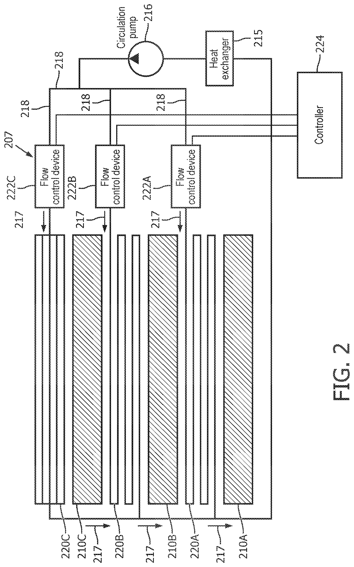
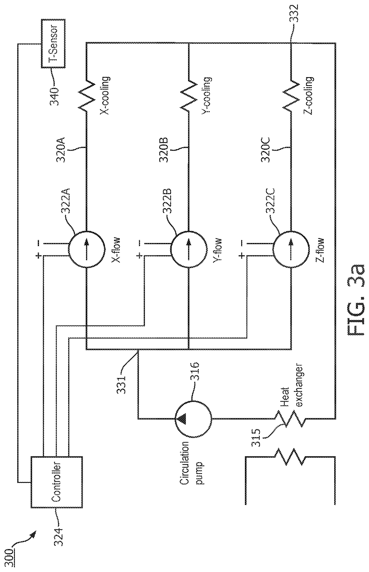
[0013]The present system and method may enable to split the coolant flow from a water cooling system (e.g. chiller) into parallel streams depending on how the gradient coils are actually used. This may particularly be useful for the so-called ZTE scanning method, where the gradient coils are on almost permanently, with slowly varying orientation of the gradient vector. Each gradient channel has an independent water cooling circuit, which can be either the hollow conductor of the gradient coil in question or a cooling system directly in contact with this gradient coil. Each of the cooling circuits has a flow control device limiting the flow rate in that particular channel or circuit. The flow control devices may be set automatically, based on predicted heat loads resulting from the scan being performed or by measuring outlet temperatures of the coolant circuits, in such a way that the flow from the chiller is optimally used.
[0016]This embodiment may be advantageous as it may prevent in advance the heating of the gradient coils based on an accurate estimation of the heat load.
[0018]According to one embodiment, the heat load is a measured outlet temperature of the coolant during the MR data acquisition. In another example, the heat load may be determined by sensing the total resistance of the individual gradient coils by measuring currents through the coils and voltages across the coils. This embodiment may enable a continuous monitoring of the heat load for enabling a timely reaction to an unexpected increase in the heat load.
[0025]According to one embodiment, the coolant tubes are hollow conductors of the gradient coils or coolant pipes in contact with the gradient coils. This may provide a compact design of the gradient coil system.

Problems solved by technology

Having multiple tubes in parallel may reduce flow resistance e.g. for cooling water.

Method used


Image

  • Gradient system with controlled cooling in the individual gradient channels
  • Gradient system with controlled cooling in the individual gradient channels
  • Gradient system with controlled cooling in the individual gradient channels

Examples


Embodiment Construction

[0037]In the following, like numbered elements in the figures are either similar elements or perform an equivalent function. Elements which have been discussed previously will not necessarily be discussed in later figures if the function is equivalent.

[0038]Various structures, systems and devices are schematically depicted in the figures for purposes of explanation only and so as to not obscure the present invention with details that are well known to those skilled in the art. Nevertheless, the attached figures are included to describe and explain illustrative examples of the disclosed subject matter.

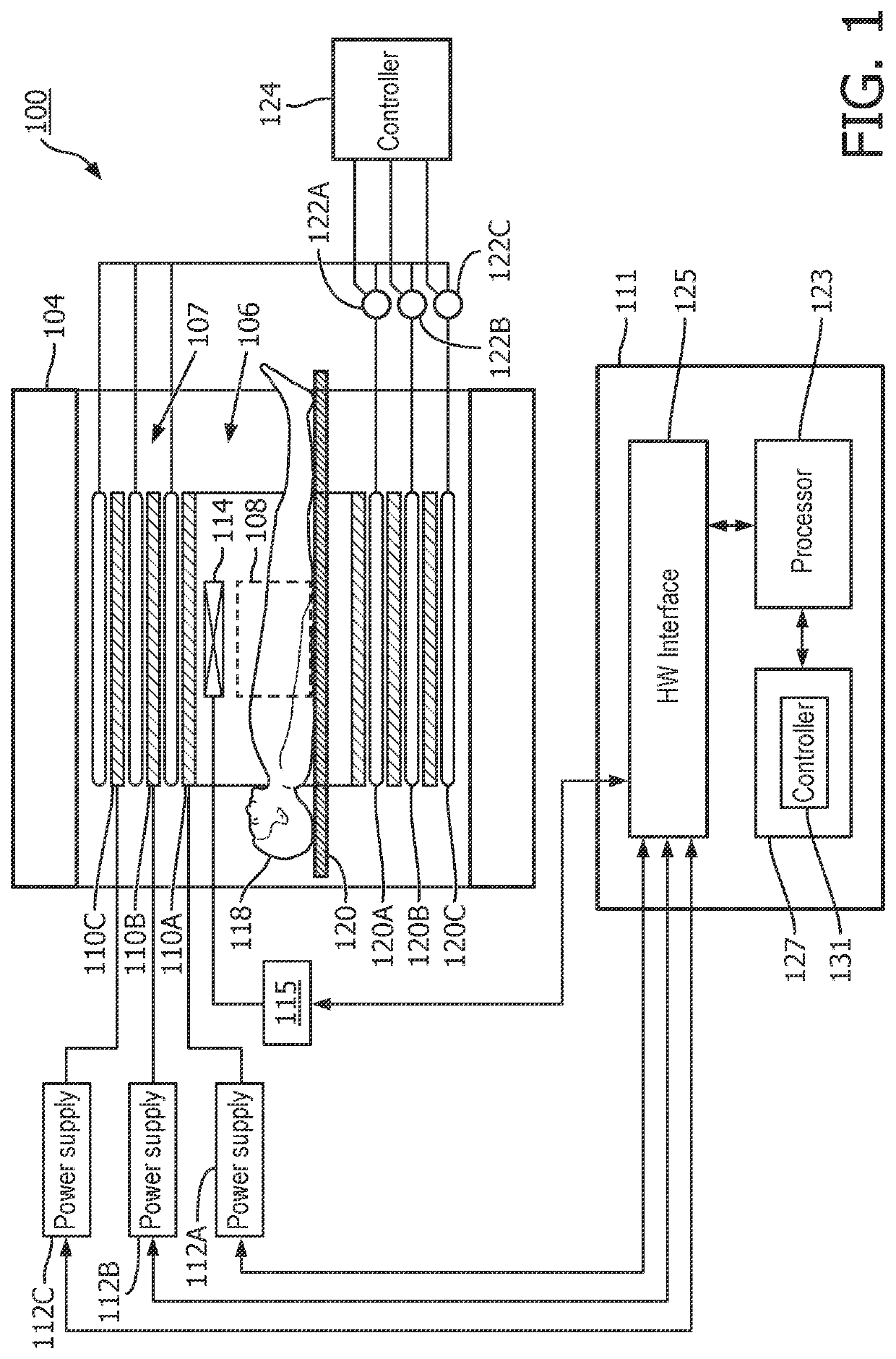
[0039]FIG. 1 illustrates a magnetic resonance imaging system 100 as an example of the medical system 100. The magnetic resonance imaging system 100 comprises a magnet 104. The magnet 104 is a superconducting cylindrical type magnet with a bore 106 in it. The use of different types of magnets is also possible; for instance, it is also possible to use both a split cylindrical magnet and a...


PUM


Abstract

A gradient coil system for a magnetic resonance imaging system includes a plurality of gradient coils for applying a gradient magnetic field to a target volume; at least one coolant tube per gradient coil for cooling the gradient coil (110A-C, 210A-C). The coolant tubes are connected to respective flow control devices and a controller, which is configured to control each flow control device of the flow control devices for adjusting the flow of a coolant in the respective coolant tube. The controller is configured to control the flow control device on the basis of heat load caused by the respective gradient coil.

Description

CROSS REFERENCE TO RELATED APPLICATIONS[0001]This application is a U.S. national phase application of International Application No. PCT / EP2018 / 054086 filed on Feb. 20, 2018, which claims the benefit of EP Application Serial No. 17156825.6 filed on Feb. 20, 2017 and is incorporated herein by reference.FIELD OF THE INVENTION[0002]The invention relates to scanning imaging systems, in particular to a cooling system for a gradient coil apparatus.BACKGROUND OF THE INVENTION[0003]A chiller utilizing water or a water and ethylene glycol mixture is typically used for removing heat from gradient coils of magnetic resonance (MR) systems. In order to minimize the flow impedance, the cooling systems consist of a number of parallel circuits served by the chiller. However, the gradient coils are not usually used at the same duty cycle and much of the capacity of the cooling system is wasted.[0004]The Japanese patent application JP H06-54819 relates to an open-type magnet with opposing pole pieces ...

Claims


Application Information

Patent Timeline
Patent Type & Authority Patents(United States)
IPC IPC(8): G01R33/385G01R33/54G01R33/56
CPCG01R33/3856G01R33/3858G01R33/543G01R33/546G01R33/56
Inventor OVERWEG, JOHANNES ADRIANUS
Owner KONINKLJIJKE PHILIPS NV
Why Eureka
Try Eureka