Ion generator and electric apparatus
a technology of electric apparatus and generator, which is applied in the direction of electrical apparatus, electric discharge tubes, corona discharge, etc., can solve the problems of difficult downsizing and difficult downsizing of ozone generators, and achieve the effect of reducing nois
- Summary
- Abstract
- Description
- Claims
- Application Information
AI Technical Summary
Benefits of technology
Problems solved by technology
Method used
Image
Examples
first preferred embodiment
[0015]The following details a preferred embodiment of the present invention.
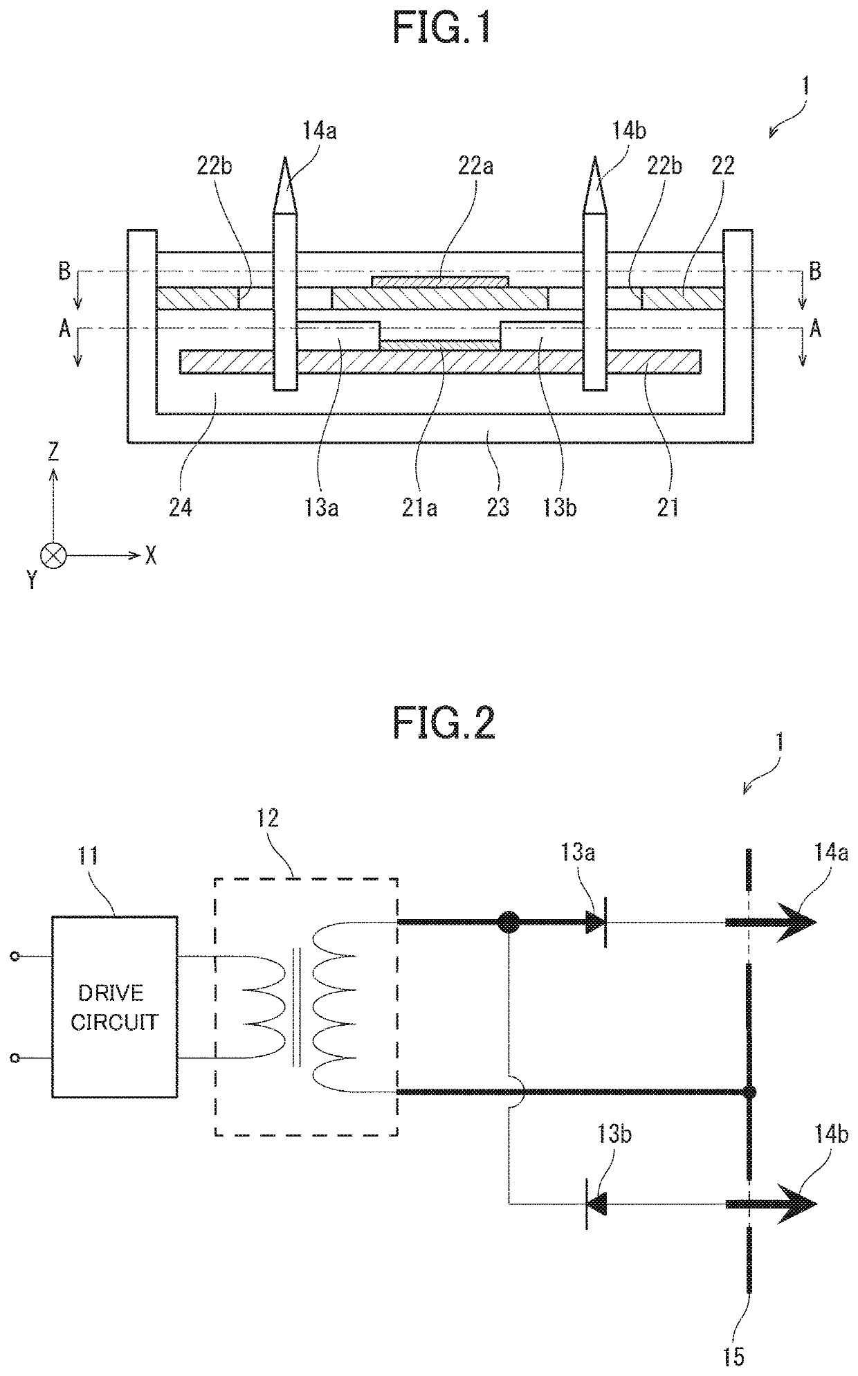
[0016]FIG. 2 schematically illustrates the circuit configuration of an ion generator 1 according to this preferred embodiment. As illustrated in FIG. 2, the ion generator 1 includes a drive circuit 11, a high-voltage transformer 12, diodes 13a and 13b, discharge electrodes 14a and 14b, and induction electrodes 15.
[0017]The drive circuit 11 is used for driving the high-voltage transformer 12 using an external input voltage. The high-voltage transformer 12 is used for boosting the input voltage when driven by the drive circuit 11.
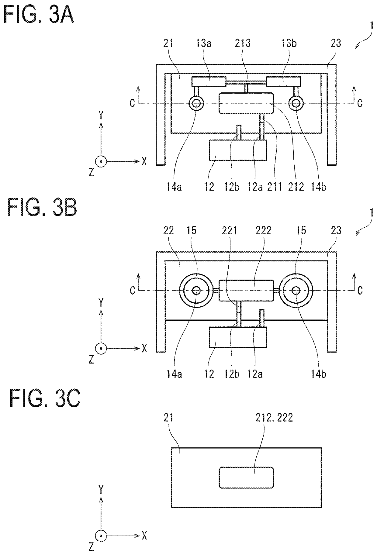
[0018]The diodes 13a and 13b are connected in parallel between a terminal 12a (c.f., FIG. 3A-FIG. 3C), one of terminals of the high-voltage transformer 12, and the discharge electrodes 14a and 14b. That is, the high-voltage transformer 12 and the discharge electrodes 14a and 14b are connected together via the diodes 13a and 13b. The anode of the diode 13a and the cathode of the diode ...
second preferred embodiment
[0040]The following describes another preferred embodiment of the present invention. For the sake of convenience in description, components whose functions are the same as those of the components described in the foregoing preferred embodiment are denoted by the same sings and will not be elaborated upon.
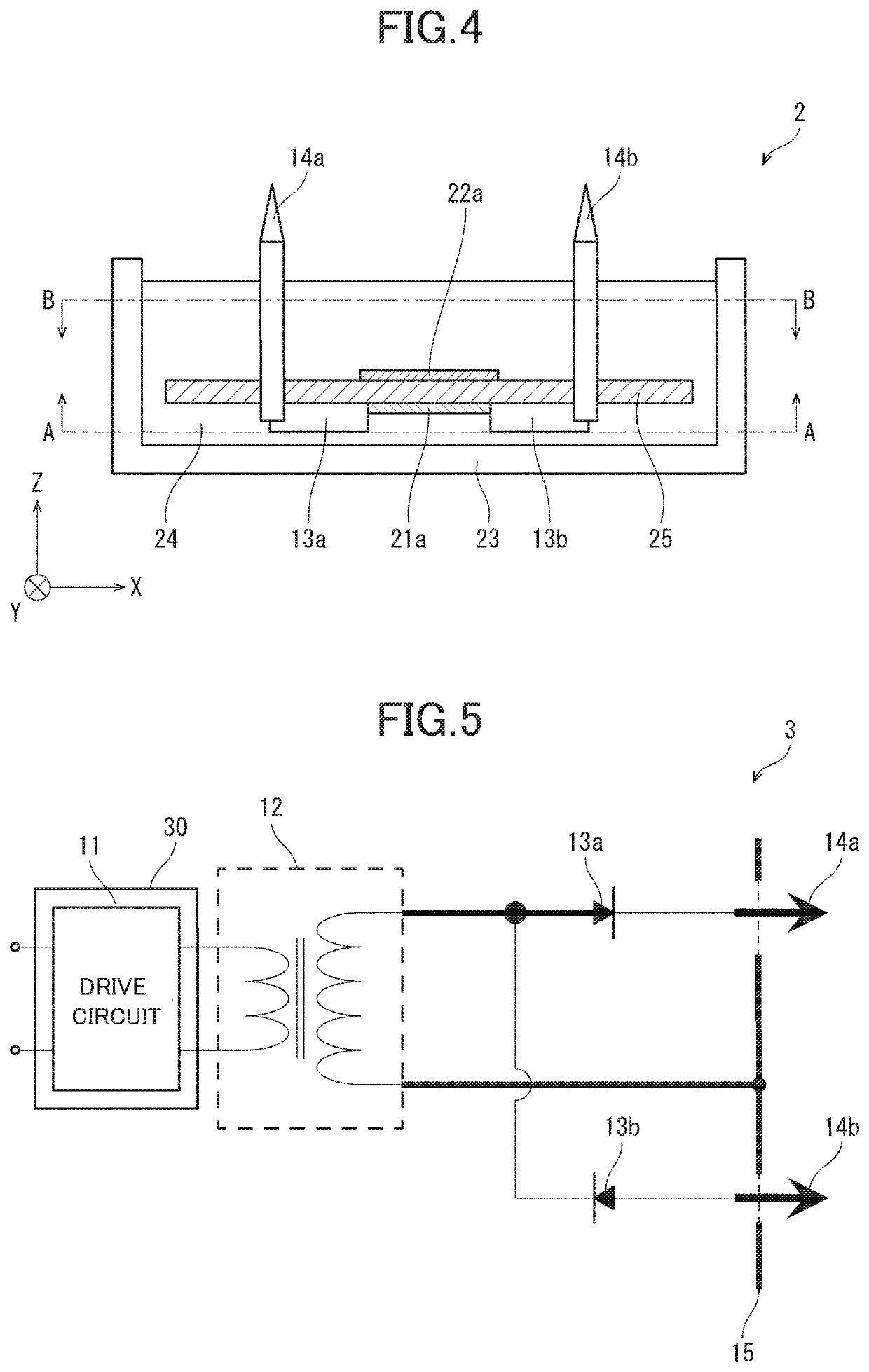
[0041]FIG. 4 schematically illustrates the configuration of an ion generator 2 according to this preferred embodiment. The ion generator 2 is different from the ion generator 1 in that the ion generator 2 includes a single substrate 25 instead of the discharge substrate 21 and induction substrate 22, as illustrated in FIG. 4. The substrate 25 may be made of a material similar to that of the discharge substrate 21 and induction substrate 22.
[0042]In the ion generator 2, the discharge wire-pattern 21a is disposed on the lower surface of the substrate 25, as illustrated in FIG. 4. In addition, the induction wire-pattern 22a is disposed on the upper surface of the substrate 25. In some ...
third preferred embodiment
[0044]FIG. 5 schematically illustrates the circuit configuration of an ion generator 3 according to still another preferred embodiment of the present invention. As illustrated in FIG. 5, the ion generator 3 includes a shield 30 in addition to the components of the ion generator 1. The shield 30 shields the drive circuit 11, disposed on the primary side of the high-voltage transformer 12, from an electromagnetic noise that occurs in the discharge wire-pattern 21a and induction wire-pattern 22a. The shield 30 may be disposed to surround the drive circuit 11 for instance, as illustrated in FIG. 5. Alternatively, the shield 30 may be disposed between the drive circuit 11 and high-voltage transformer 12. Alternatively, the shield 30 may be disposed to surround the high-voltage transformer 12.
[0045]The ion generator 3, which is configured in a manner similar to the ion generator 1, reduces a noise. The shield 30 can be thus simply configured when compared to, for instance, the ozone gener...
PUM
| Property | Measurement | Unit |
|---|---|---|
| voltage | aaaaa | aaaaa |
| width | aaaaa | aaaaa |
| external input voltage | aaaaa | aaaaa |
Abstract
Description
Claims
Application Information
 - R&D
- Intellectual Property
- Life Sciences
- Materials
- Tech Scout
- Unparalleled Data Quality
- Higher Quality Content
- 60% Fewer Hallucinations
Browse by: Latest US Patents, China's latest patents, Technical Efficacy Thesaurus, Application Domain, Technology Topic, Popular Technical Reports.
© 2025 PatSnap. All rights reserved.Legal|Privacy policy|Modern Slavery Act Transparency Statement|Sitemap|About US| Contact US: help@patsnap.com


