Plastic container body and container closure and carry handle grip / container leverage opening tool assembly

a technology for plastic containers and closures, applied in the field of containers, can solve the problems of not meeting the performance and handling market expectations of various known and consumer-requested performance and consumer-requested products, the conventional plastic container locking mechanism cannot withstand external force during normal use, and the elaborate design of sealing devices is usually relatively expensive to manufactur

Active Publication Date: 2021-05-25
TYLER GLENN NORMAN +1
View PDF5 Cites 5 Cited by
  • Summary
  • Abstract
  • Description
  • Claims
  • Application Information

AI Technical Summary

Benefits of technology

[0017]It is another object of the present invention to provide a container cover and container body locking mechanism which can withstand a strong force when applied across and along the vertical and / or radial axis of the corresponding container body and closure locking mechanisms.
[0018]Other objects of the present invention are to provide a seal-able container to hold flow-able substances, which is inexpensive to manufacture, is reusable, provide a reliable airtight and liquid tight locking and sealing mechanism and continue to do so when opened and closed a great number of times and when in use.
[0023]The annular skirt of the container lid includes an annular, angular and elastic ring band which after engagement onto the container body in its locked and scaled condition may be physically inverted and folded upwards and away from the corresponding container body outer skirt annular notch groove enabling container opening in a safe, easy and ergonomic manner.
[0025]Even furthermore the present invention includes a plurality of air pressure evacuation vent channels and ports to aid in the normalization of the internal pressure of the container and when subjected to various atmospheric and ambient temperature conditions particularly when being transported on an open back lorry or stored in direct sunlight.

Problems solved by technology

Ordinary prior art wide-mouthed plastic pail and closure containers suffer distinct disadvantages with regard to meeting various known and consumer requested performance and handling market expectations.
Prior art containers which have effective sealing devices are usually elaborately designed and are relatively expensive to manufacture due to the need to have vulcanized rubber O-ring seals to achieve effective and reliable seal-ability.
Furthermore conventional plastic container locking mechanisms cannot withstand force exerted externally during normal use.
Conventional plastic containers also are not capable of being stacked one on top of another in a warehouse, as the lower units become distorted due to the increased top load weight mainly due to lid deformation.
Even furthermore conventional prior art container designs that comply with market tamper evidence requirements are often extraordinarily difficult to open with the need to use tools such as knives, cutters and levers which may cause serious injury.
Another most serious negative disadvantage of ordinary prior art containers, and those that achieve absolute internal leak proof and air tight seal ability, is the negative affect when the air space above the packaged liquid and the underside of the container lid, commonly known as the container ullage, is exposed and or subjected to increased external heat and or when there is a change in the outer atmospheric pressure.
Container cover bulging and distortion including the ultimate leakage of the packaged fluid will occur when the filled containers are transported, for instance sake, from sea level to higher altitudes and over rough terrain.
Furthermore, and when these containers are exposed to an increase in external ambient heat the container cover centre recessed panel bulges outwards making stacking of multiple containers (4-5 high) in a single unsupported column impossible.

Method used


Image

  • Plastic container body and container closure and carry handle grip / container leverage opening tool assembly
  • Plastic container body and container closure and carry handle grip / container leverage opening tool assembly
  • Plastic container body and container closure and carry handle grip / container leverage opening tool assembly

Examples


Embodiment Construction

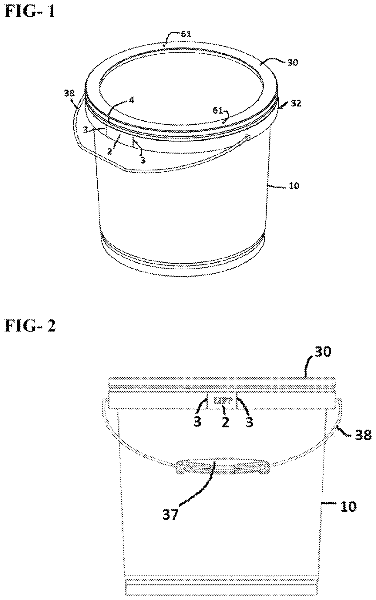
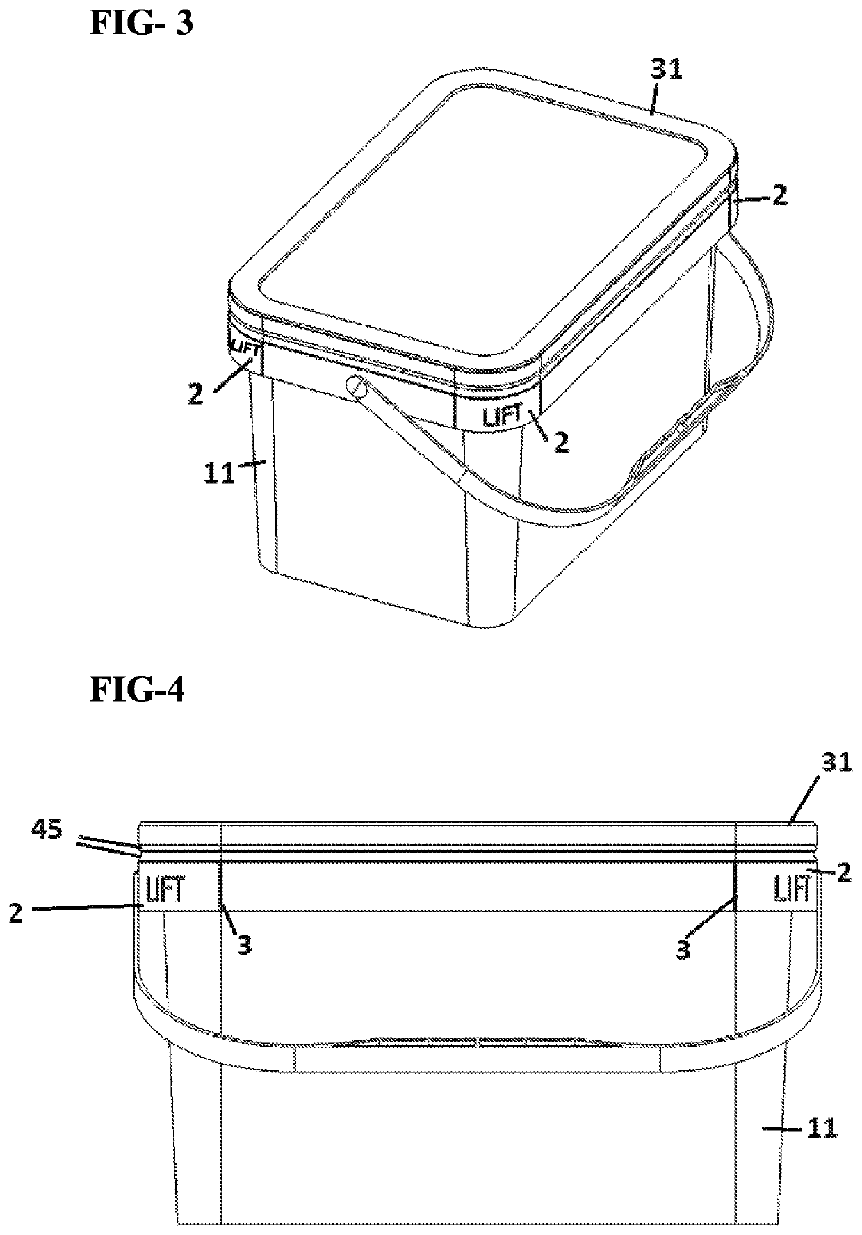
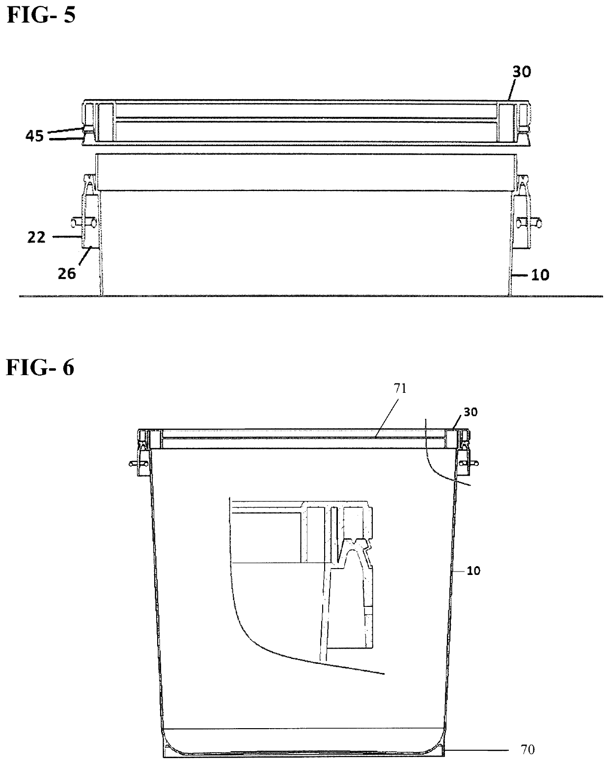
[0052]The container body [10] has an open top [12] with a rim [14] there around. An annular skirt [24] extends radially outwards adjacent to the base of the rim wall [14] which includes a radially upward and outward annular flange [16] with an inner annular flange [18] and an outward annular flange [20] in a concentric spaced apart relation to the inner annular flange. Preferably the outer annular flange [20] is angled at the top outer corner so as to allow for engagement with the container closure [30] mating profile [45].

[0053]The container body [10] annular flange [22] includes an annular notch [25] which creates an engagement recess slot for the container closure [30] corresponding annular and angled elastic flange [45] which creates the effective locking and sealing condition and upon container member part engagement. FIG. 7 and FIG. 8 clearly illustrates such accurate and positive engagement.

[0054]To provide rigidity and to provide a means to absorb lateral impact force applie...


PUM


Abstract

A plastic injection moulded wide mouth container body and container cover locking and sealing mechanism which includes an annular flange and an annular angular notch groove respectively in a pre-determined configuration so as to provide a tight leak-proof seal when the container lid is fitted over, around and within the container body hoop annular fin and upon locking engagement. The present invention incorporates a multi-use plastic handle grip which may also be used as a closure opening levering tool to disengage the container lid from the container body in a safe and ergonomic manner. More significantly the invention, and when in use and upon first usage opening, does not require the removal of any portion of the container lid to comply with tamper evident requirements, nor needs other tools such as knives and metal levers to completely remove the container closure from the container body. Still furthermore the invention includes a plurality of venting channels and adjacent ports which allows the evacuation of increased internal air pressure within the closed container head space with no leakage of the packaged fluid product. The invention may be adapted to plastic containers of any size and shape being round, oval, square or rectangular tapered or straight wall containers.

Description

TECHNICAL FIELD[0001]The present invention relates to a container and in particular to An improved container cover and container body locking mechanism which will prevent contents from the assembled container from flowing out when the container is displaced from its vertical axis.[0002]The invention further relates to a container cover and container body locking sealing-mechanism which does not separate or leak when the container is subjected to a free fall around its axis from a height of about 1.0 meter.[0003]Furthermore the invention relates to a container cover which may be easily, safely and ergonomically detached from the container pail by using another embodiment of the invention being the detachable plastic handle grip. When the plastic handle grip is removed from the fitted wire handle it may be used as a lever to firstly pivotally and partially separate and or shear the integral lever panel of the container pail hoop which when in motion turns the container cover outer ann...

Claims


Application Information

Patent Timeline
Patent Type & Authority Patents(United States)
IPC IPC(8): B65D43/06B65D43/02B65D51/16B44D3/12B65D25/00B65D25/28
CPCB65D43/0245B44D3/127B65D25/00B65D25/2852B65D43/06B65D51/16B65D51/1688B65D2543/005B65D2543/00092B65D2543/00194B65D2543/00296B65D2543/00453B65D2543/00657B65D43/0212B65D2543/00175B65D2543/00518B65D2543/00555B65D2543/00629B65D2543/00685B65D2543/00759B65D2543/00796B65D2543/00888B65D2401/10
Inventor TYLER, GLENN NORMANKANG, KEM WEICHOREAK
Owner TYLER GLENN NORMAN
Why Eureka
Try Eureka