Methods of managing solvent inventory in a gravity drainage extraction chamber

a gravity drainage and extraction chamber technology, applied in the field of hydrocarbon extraction, can solve the problems of reducing the amount of liquid solvent in the chamber that is not being productive, affecting drainage fluids by elevated temperature, and reducing the volume used in the nsolv® condensing solvent process, so as to reduce the amount of liquid solvent, reduce operating and capital costs, and reduce the solvent to oil ratio

Active Publication Date: 2021-06-01
HATCH LTD
View PDF5 Cites 0 Cited by
  • Summary
  • Abstract
  • Description
  • Claims
  • Application Information

AI Technical Summary

Benefits of technology

[0010]What is desired therefore are methods to reduce the amount of liquid solvent which may be present in the extraction chamber and to reduce the solvent to oil ratio of the process. Preventing solvent from condensing in unproductive areas such as in the internal casing of the well bore, the already extracted zone in the chamber or even parts of the overburden, may also be desirable to reduce operating and capital costs. It may further be desirable to have methods to mitigate the increased solvent demand due to heat loss to unproductive areas and short-circuiting as the chamber grows in size, as with a larger size such effects may become ever more dominant. It may be desirable to allow non-condensable gasses to be removed from the chamber during such a process as well as limiting the demobilization of bitumen in inopportune locations by flashing off the solvent in situ from a mixed draining fluid. The present invention may address some of the issues of the prior processes through careful attention to process parameters and extraction chamber dynamics.
[0011]According to the present invention one method by which these problems may be addressed is to, in conjunction with a formed extraction chamber, increase the bottom hole temperature at or above the injector elevation so that it is above the dew point of the injected solvent, such that the solvent will remain as mostly vapour in the hot zone of the chamber and only reach its bubble point at the extraction surface. The higher temperature of the injected solvent provides sensible heat that is used to vapourize condensed or liquid solvent within the chamber, thus reduces the liquid solvent within the chamber that is not being productive. This may reduce the solvent volume used in the Nsolv® condensing solvent process. What is desired is to do so without creating any in situ barriers for draining fluids or for non-condensable gas removal. In this sense, the present invention may provide a heated zone locally around the injector which extends into the extracted portion of the chamber. A heated zone in this sense means that the temperature of the heated zone is above the condensation temperature of the solvent at the extraction interface, to promote vaporization of any liquid solvent passing through the heated zone.
[0016]The application of the temperature increase to the extracted volume may be beneficial after the extraction chamber has grown enough that it has reached top of pay when the heat losses to the overburden are much higher than a young chamber. At this time, the draining liquids above the heated zone will be hydrocarbon lean. If the increased injector bottom hole temperature is applied too early or is set too high, when the chamber is too small, the drainage fluids may be affected by the elevated temperature. This may cause the dissolved solvent and non-condensables in the drainage fluids to vapourize from the drainage fluid, rendering the heavy oil in the drainage fluid relatively immobile at certain conditions thereby creating a drainage barrier as was postulated in conjunction with the Thermal Solvent process described above. The present invention comprehends a balance between increasing the heat deposited to the extracted volume and simply increasing the amount of solvent being injected to satisfy the growing demand for solvent in a growing chamber with an expanding extraction surface.
[0017]In another aspect, the present invention may limit or not apply an increase in temperature to the extracted volume until there is sufficient extracted volume adjacent to the heated zone to permit mixed fluids (solvent and hydrocarbons being recovered) to drain to the production well without passing through the heated zone and therefore without flashing off the solvent.
[0023]Co-injecting a vapour energy carrier, for example steam, that may preferentially condense near the injection well bore to create a local heat effect.
[0025]In some cases, the central process facility may be located a significant distance from the individual well pads, which may lead to appreciable heat losses to superheated solvent or other heated injection fluids before it can reach the injector bottom hole. Therefore, the present invention may also contemplate vapourizing and / or heating the solvent or other heating injection fluids at the well pad, rather than solely at the central process facility to achieve the bottom hole temperature target. Heating at the well pad may provide cost efficiencies for injecting larger volumes of vapour due to superheat. Furthermore, bottom hole electric heaters or hot tubing containing a circulating heat transfer fluid may be employed to similar effect. Hot tube surfaces primarily relying on conductive heat transfer tend to deliver a lower heat intensity per unit length, due to the relatively low heat transfer coefficient to a convective gas, therefore it may be necessary to equip the tubes with heat transfer enhancing fins or to deploy the tubes directly into the sand matrix.

Problems solved by technology

The higher temperature of the injected solvent provides sensible heat that is used to vapourize condensed or liquid solvent within the chamber, thus reduces the liquid solvent within the chamber that is not being productive.
This may reduce the solvent volume used in the Nsolv® condensing solvent process.
If the increased injector bottom hole temperature is applied too early or is set too high, when the chamber is too small, the drainage fluids may be affected by the elevated temperature.
This may cause the dissolved solvent and non-condensables in the drainage fluids to vapourize from the drainage fluid, rendering the heavy oil in the drainage fluid relatively immobile at certain conditions thereby creating a drainage barrier as was postulated in conjunction with the Thermal Solvent process described above.

Method used


Image

  • Methods of managing solvent inventory in a gravity drainage extraction chamber
  • Methods of managing solvent inventory in a gravity drainage extraction chamber
  • Methods of managing solvent inventory in a gravity drainage extraction chamber

Examples


Embodiment Construction

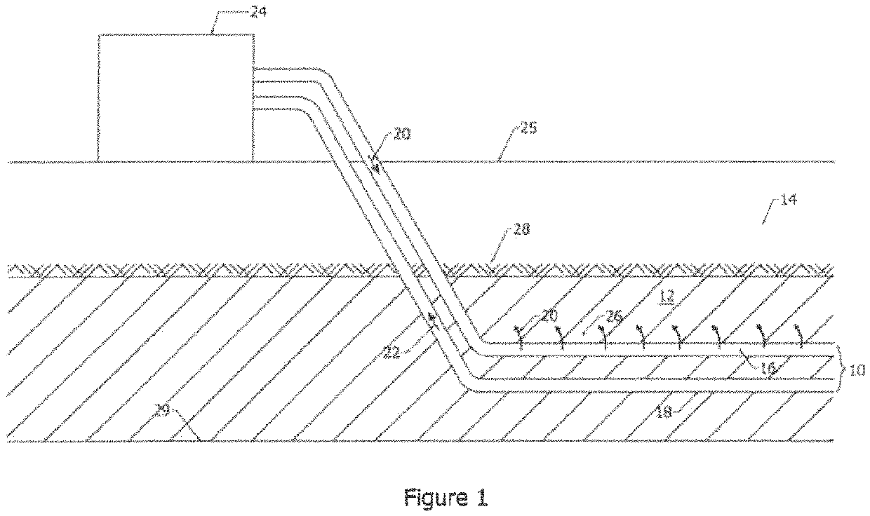
[0048]As shown in FIG. 1, the underground facilities may consist of one or more horizontal well pairs 10 located in a pay zone 12 of an underground formation 14, with the upper well 16 of the well pair being an injector well and the lower well 18 being a production well. A condensing solvent 20 is placed into the formation 14 through the injection well 16. Although many solvents 20 are comprehended by the present invention, butane may be used as an example for the solvent, since it has a reasonable condensing temperature at a reasonable pressure for a shallow, but not untypical pay zone in the Alberta oil sands, such as the MacKay River deposit. Propane, ethane, pentane, dimethyl ether, H2S, ammonia, COS, other light ethers, light aromatics and the like may also be suitable solvents in some cases. Any solvent that is compatible with the Nsolv® process is suitable for this invention as well. Mixed production fluids 22 are brought up from the production well 18 to a surface plant 24, ...


PUM


Abstract

A method of managing a liquid solvent inventory in a condensing solvent gravity drainage extraction chamber includes growing the extraction chamber by injecting a solvent vapour under conditions which cause at least a portion of the solvent vapour to condense on a hydrocarbon extraction interface at a condensation temperature, then accumulating within the extraction chamber condensed liquid solvent which is draining through the chamber under the influence of gravity, which liquid solvent includes a hydrocarbon rich fluid production layer which is proximal to said extraction interface, and then heating a portion of the extraction chamber from a location near, in and / or above the injector to create a heated zone having a temperature above the condensation temperature without heating the hydrocarbon rich production layer to permit the hydrocarbon rich production layer to continue to drain to a production well.

Description

CROSS REFERENCE TO RELATED APPLICATIONS[0001]This application is a National Stage Application pursuant to 35 U.S.C. 371, claiming priority to PCT Application Number PCT / CA2018 / 000142 filed on Jul. 18, 2017.FIELD OF THE INVENTION[0002]This invention relates generally to the field of hydrocarbon extraction and most particularly to EOR (Enhanced Oil Recovery) as applied to unconventional resources such as the Canadian oil sands. One type of EOR is a solvent based in situ gravity drainage extraction process. In particular, this invention relates to methods for managing a condensing solvent in situ gravity drainage extraction process. Most particularly this invention relates to methods and apparatuses which may be used to manage or optimize the amount of solvent required in a formed extraction chamber.BACKGROUND OF THE INVENTION[0003]Many attempts have been made to extract in situ hydrocarbons from deposits which do not readily flow at reservoir conditions, such as the Canadian oil sands...

Claims


Application Information

Patent Timeline
Patent Type & Authority Patents(United States)
IPC IPC(8): E21B43/24E21B47/07
CPCE21B43/2408E21B43/2401E21B43/2406E21B47/07
Inventor EICHHORN, MARK ANTHONYKRAWCHUK, PAULBAWA, GHARANDIP SINGHBLACKMORE, ADAM DOUGLASLEE, CASSANDRA AMANDA
Owner HATCH LTD
Why Eureka
Try Eureka