Battery structure and protector

a battery structure and electric vehicle technology, applied in the direction of battery/fuel cell control arrangement, cell components, battery/metal/composite material, etc., can solve the problems of consuming a large amount of space between the underride protection and the parts to be protected, and the protection known from the prior art is either made from metal or composite materials, so as to achieve less space in the height direction, improve performance, and reduce the effect of local stress

Active Publication Date: 2021-06-15
MUBEA CARBO TECH GMBH
View PDF14 Cites 3 Cited by
  • Summary
  • Abstract
  • Description
  • Claims
  • Application Information

AI Technical Summary

Benefits of technology

[0009]Therefore, it is an object of the present disclosure to provide an improved protector for a battery structure which offers better performance for protecting of a battery structure in an underfloor of an electric vehicle, namely high local stress, e.g. due to impact by an immersible traffic bollard. It is a further object to provide a protector which is lighter and needs less space in height direction to deplete the occurring energy by elastic and / or plastic deformation.
[0010]The protector according to the present disclosure helps to prevent damage of at least one battery module arranged in an underfloor of an electric car. The protector normally comprises a top belt and a bottom belt and a there between arranged core interconnecting the top belt and the bottom belt. The top belt preferably has a waveform in at least one direction. Depending on the field of application, the waveform may extend in two directions arching from one beam to another beam effectively receiving and distributing high local load as described hereinafter in more detail. The protector according to the present disclosure offers optimized distribution of the occurring energy into the structure by a combination of elastic and / or plastic deformation. The top belt and the bottom belt, as well as the there-between arranged core, are preferably made from at least one out of the following group of materials: Aluminum, steel, fiber reinforced composite material, thermoplastic material.
[0014]The protector is preferably interconnected to at least longitudinal and / or at least one transverse beam of the battery case. In a variation the longitudinal and the transverse beams are arranged grid-like. The top belt can be interconnected to a frame of the battery case. The protector is preferably arranged below a lower sled wall of the battery case housing with the at least one battery module inside. One aim is that the risk that an impacting object can reach the lower sled wall is significantly reduced.

Problems solved by technology

The protectors known from the prior art are either made from metal or composite material and are not appropriate for absorbing high punctual impact loads.
One disadvantage of the systems known from the prior art is that a significant amount of space between the underride protection and the parts to be protected is consumed as the structure used to fulfill the requirements, i.e. depleting of the introduced energy without significant introduction of forces into the parts to be protected.

Method used


Image

  • Battery structure and protector
  • Battery structure and protector
  • Battery structure and protector

Examples


Embodiment Construction

[0022]Reference will now be made in detail to certain embodiments, examples of which are illustrated in the accompanying drawings, in which some, but not all features are shown. Indeed, embodiments disclosed herein may be embodied in many different forms and should not be construed as limited to the embodiments set forth herein; rather, these embodiments are provided so that this disclosure will satisfy applicable legal requirements. Whenever possible, like reference numbers will be used to refer to like components or parts.

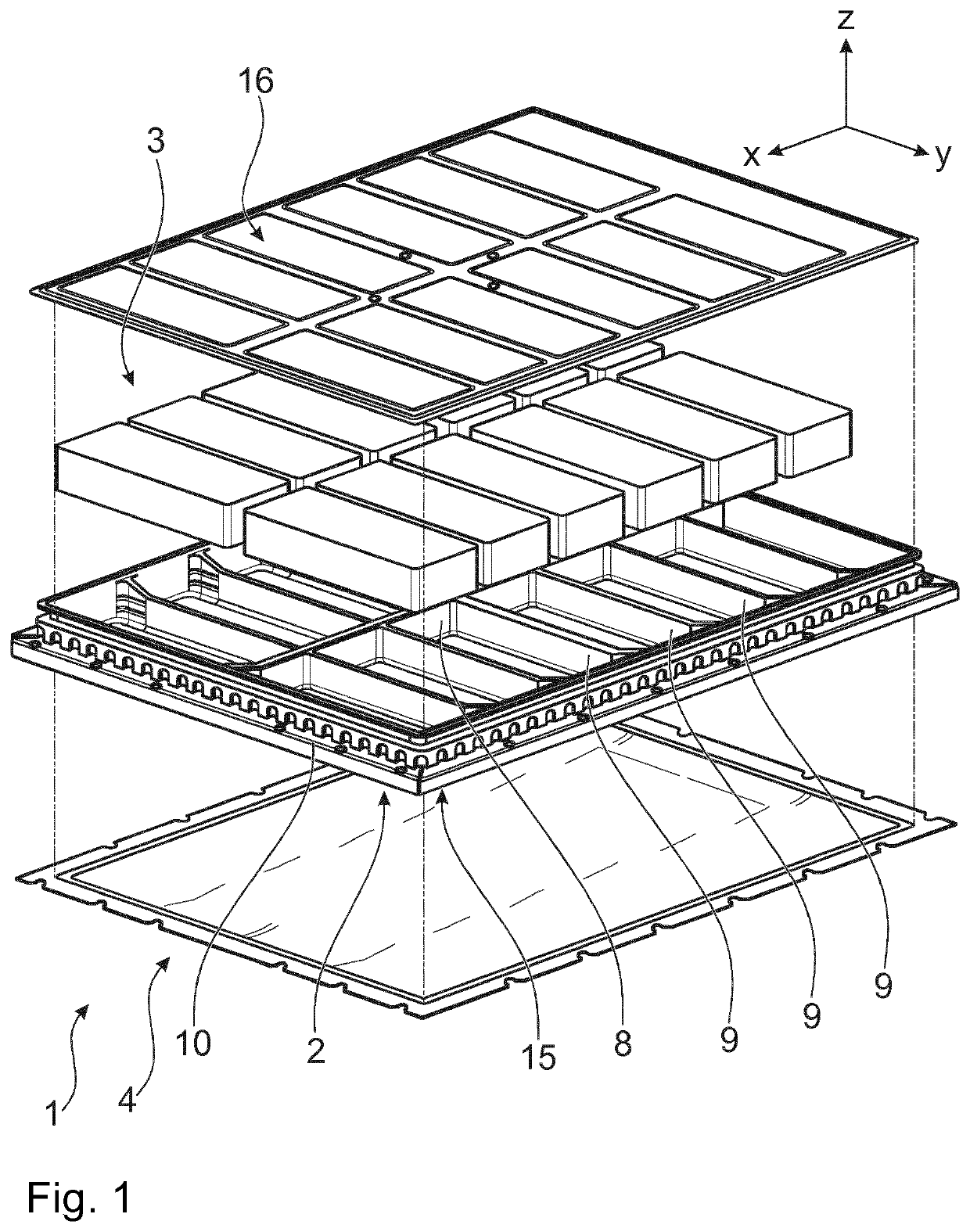
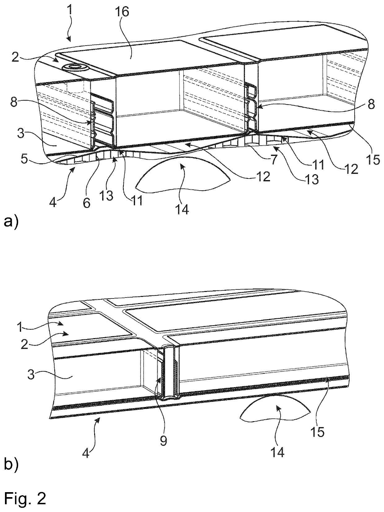
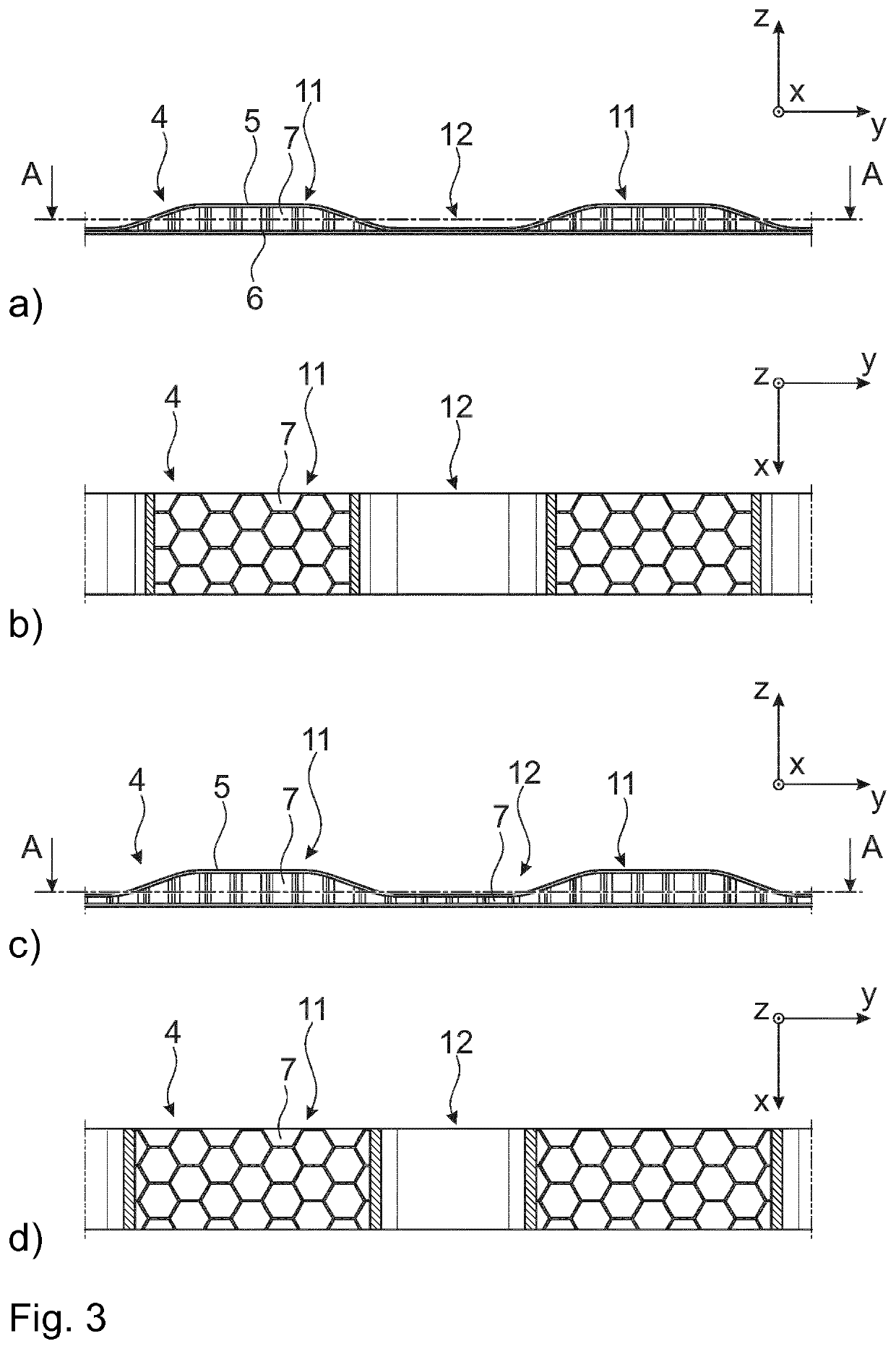
[0023]FIG. 1 shows a battery structure 1 in an exploded view from below. FIGS. 2a and 2b schematically show an impact of an object 14 into a battery structure 1 from below. FIG. 3a through 3d show cross-section views of a first and a second variation of a protector 4 from the side along section line A-A. FIG. 4 shows a third variation of a protector 4 in a perspective view.

[0024]As shown in FIG. 1, the battery structure 1 comprises a battery case 2 for at least o...


PUM

PropertyMeasurementUnit
elevationsaaaaaaaaaa
areaaaaaaaaaaa
thermally conductiveaaaaaaaaaa

Abstract

The present disclosure relates to a battery structure for an electric vehicle. The battery structure comprises a battery case for at least one battery module and a protector including a top belt, a bottom belt and a core arranged between and interconnecting the top belt and the bottom belt. The top belt has a wavelike cross section.

Description

CROSS-REFERENCE TO RELATED APPLICATIONS[0001]This application claims the benefit of the filing date of international PCT Application No. PCT / EP2018 / 053354, filed on Feb. 9, 2018 that in turn claims priority to Swiss Patent Application No. CH 00186 / 17, filed on Feb. 17, 2017, which are hereby incorporated by reference in their entirety.FIELD OF THE INVENTION[0002]The present disclosure relates to a battery structure for an electric vehicle and a protector for a battery pack.BACKGROUND OF THE INVENTION[0003]DE102015101096A1 was first published in July 2016 in the name of Porsche AG. It relates to a battery structure. The battery facilities include an underbody battery between a bottom plate and a floor. At least one deformation zone is foreseen to avoid unwanted damage to a battery of the underbody. The deformation zone is below the battery facilities. The bottom plate can deform upwards.[0004]W015077000A1 was first published in May 2015 in the name of Atieva Inc. It relates to a batt...

Claims


Application Information

Patent Timeline
Patent Type & Authority Patents(United States)
IPC IPC(8): H01M4/02B60K1/04H01M10/613H01M10/625H01M10/647H01M10/6556B60L58/27B60L50/64B60L50/60B60L58/26H01M50/20B60K1/00H01M50/204
CPCB60K1/04B60L50/64B60L50/66B60L58/26B60L58/27H01M10/613H01M10/625H01M10/647H01M10/6556H01M50/20B60K2001/005B60K2001/0438B60Y2306/01B60Y2306/05H01M2220/20H01M50/242H01M50/249H01M50/204H01M10/615H01M50/289B60L2240/545Y02E60/10
Inventor SPIELVOGEL, BERNHARDSCHMITZ, SEBASTIANINSAM, GUIDODORFINGER, HERBERT
Owner MUBEA CARBO TECH GMBH
Why Eureka
Try Eureka