Magnetic field sensing device

a magnetic field and sensing device technology, applied in the field of magnetic field sensing devices, can solve the problems of reducing the stability of configuring the magnetization direction in the pinned layer, and the cost is considered to be increased, so as to improve the stability of the magnetization state of the vortex magnetoresistors, reduce manufacturing costs, and improve the effect of the magnetic sta

Active Publication Date: 2021-06-15
ISENTEK INC
View PDF8 Cites 0 Cited by
  • Summary
  • Abstract
  • Description
  • Claims
  • Application Information

AI Technical Summary

Benefits of technology

[0007]In the magnetic field sensing device provided by the embodiment of the invention, the direction of the magnetic field is changed by using the magnetic flux concentrating module, and the pinning direction of the vortex magnetoresistors is inclined with respect to the sides of the magnetic flux concentrating module. Thus, the sensing of the magnetic field components in different directions can be achieved by using the vortex magnetoresistors having the same pinning direction. In this way, the magnetic field sensing device provided by the embodiment of the invention has a simple and stable manufacturing process and lower manufacturing cost, and thereby, a magnetization state of the vortex magnetoresistors can be more stable.

Problems solved by technology

However, from a point of view of manufacturing, manufacturing a second pinning direction for the pinning layer in a wafer may cause considerable increase in the cost and result in reduction in stability of configuring a magnetization direction in the pinned layer.

Method used


Image

  • Magnetic field sensing device
  • Magnetic field sensing device
  • Magnetic field sensing device

Examples


Embodiment Construction

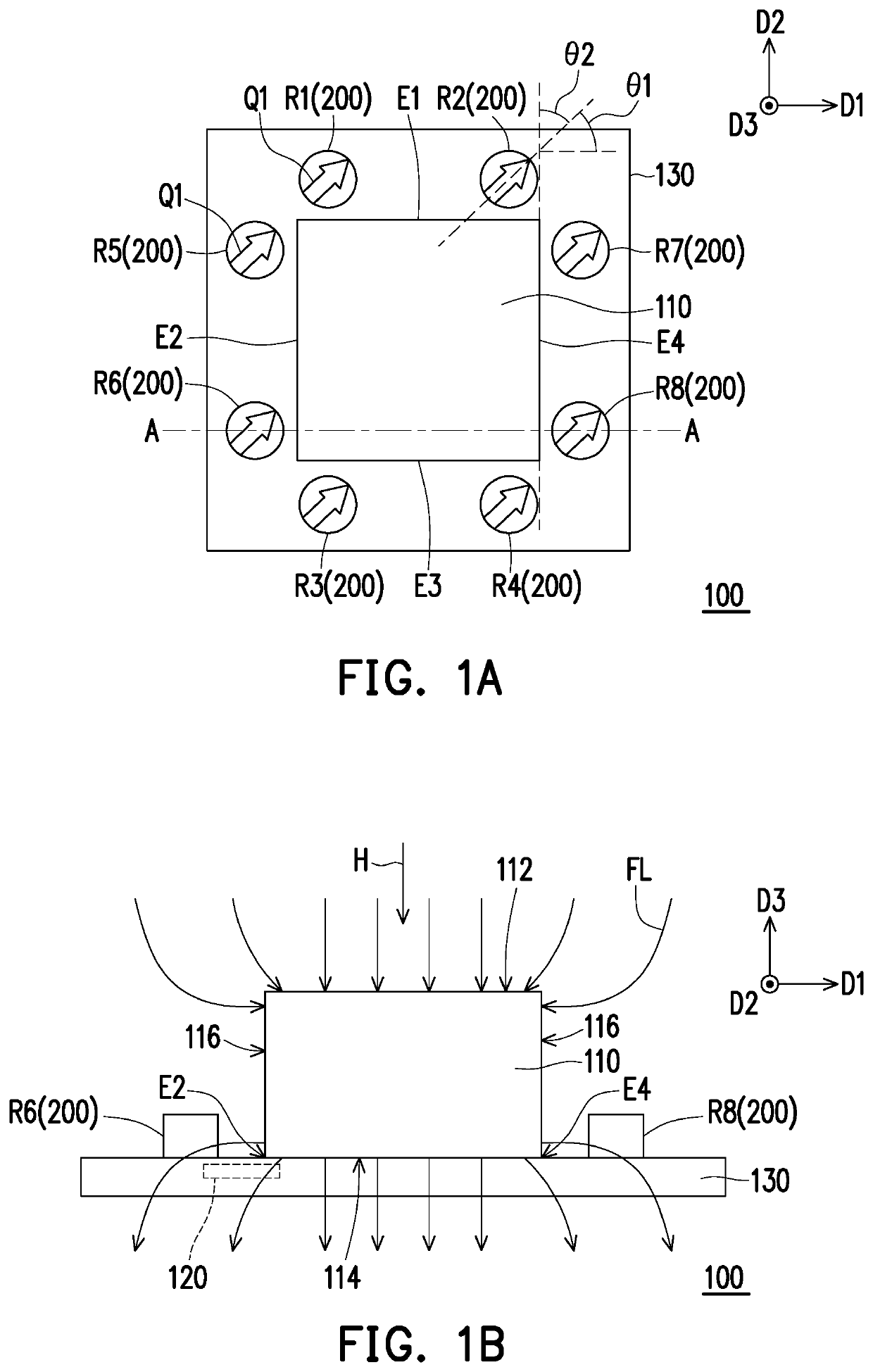
[0027]FIG. 1A is a schematic top-view diagram illustrating a magnetic field sensing device according to an embodiment of the invention. FIG. 1B is a schematic cross-sectional diagram illustrating the magnetic field sensing device depicted in FIG. 1A along line A-A′. Referring to FIG. 1A and FIG. 1B, a magnetic field sensing device 100 of the present embodiment includes a magnetic flux concentrating module 110 and a plurality of vortex magnetoresistors 200. The magnetic flux concentrating module 110 has a first side E1, a second side E2, a third side E3 and a fourth side E4, wherein the first side E1 is parallel to the third side E3, the second side E2 is parallel to the fourth side E4, and the first side E1 is not parallel to the second side E2. In the present embodiment, the first side E1 is perpendicular to the second side E2. Additionally, in the present embodiment, the magnetic flux concentrating module 110 is a single magnetic flux concentrator, and the first, the second, the t...


PUM

PropertyMeasurementUnit
included angleaaaaaaaaaa
included angle θ2aaaaaaaaaa
magnetic fieldaaaaaaaaaa

Abstract

A magnetic field sensing device including a magnetic flux concentrating module and a plurality of vortex magnetoresistors is provided. The magnetic flux concentrating module has a first side, a second side, a third side and a fourth side, wherein the first side is parallel to the third side, the second side is parallel to the fourth side, and the first side is not parallel to the second side. The vortex magnetoresistors are disposed beside the first to the fourth sides. The vortex magnetoresistors have a same pinning direction. The pinning direction is inclined with respect to the first side and the second side. The vortex magnetoresistors are configured to be connected to form a plurality of different Wheatstone bridges, so as to sense magnetic field components in a plurality of different directions, respectively.

Description

CROSS-REFERENCE TO RELATED APPLICATION[0001]This application claims the priority benefits of U.S. provisional application Ser. No. 62 / 718,973, filed on Aug. 15, 2018, and Taiwan application serial no. 108118916, filed on May 31, 2019. The entirety of each of the above-mentioned patent applications is hereby incorporated by reference herein and made a part of this specification.BACKGROUNDField of the Invention[0002]The invention relates to a magnetic field sensing device.Description of Related Art[0003]A magnetic field sensor is an important component capable of providing a system with an electronic compass and a motion tracking function. In recent years, related applications thereof are rapidly developed, particularly those for portable devices. In new generation of applications, high accuracy, quick response, a small volume, low power consumption and reliable quality have become essential features of the magnetic field sensor.[0004]A conventional giant magnetoresistor or a tunnelin...

Claims


Application Information

Patent Timeline
Patent Type & Authority Patents(United States)
IPC IPC(8): G01R33/09
CPCG01R33/091G01R33/093G01R33/098G01R33/096G01R33/0011G01R33/0094
Inventor YUAN, FU-TE
Owner ISENTEK INC
Why Eureka
Try Eureka