Turbo molecular pump for mass spectrometer

a molecular pump and mass spectrometer technology, applied in the direction of turbines, liquid fuel engines, particle separator tubes details, etc., can solve the problems of increasing the overall system size, the material strength of the blades of the turbo molecular pump presently commercially available is already optimized, and the overall system size cannot be substantially improved, so as to achieve the effect of reducing the overall form factor, reducing the size of the overall system, and optimizing the pumping speed

Active Publication Date: 2021-06-15
BRUKER DALTONIK GMBH & CO KG
View PDF24 Cites 0 Cited by
  • Summary
  • Abstract
  • Description
  • Claims
  • Application Information

AI Technical Summary

Benefits of technology

[0019]The present invention makes use of one or more novel cage-like rotor stages, as the case may be, in addition to conventional rotor stages often used in the art, to optimize pumping speed on vacuum systems with low gas flows and low ultimate pressures. This allows for a smaller motor as well as smaller overall form factor and makes it well suited, in particular, for compact mass spectrometers (MS) and desk-top mass spectrometers.
[0021]The basic idea of the present disclosure is to complement the traditional, merely radially extending rotor blades in a first rotor stage located at the low pressure input region with a cage-like setting having a set of additional paraxial rotor blade portions connected, preferably in one piece, to the well-known top radial rotor blade portion. In such design, the rotor blade portions cover both the circumference and top of the notional rotor “cage”. In so doing and providing for the paraxial rotor blade portions of such turbo molecular pump being at least partially (and preferably fully) fluidically exposed to the volume to be evacuated, the pumping speed can be substantially increased because it is proportional both to the blade speed as well as the rotor blade portion length along the rotational axis. In addition, it becomes possible to also extract gaseous matter perpendicularly to the rotor axis (drive shaft axis), and this in principle along the whole circumference of 360 degrees around the pump rotor stage which correspondingly increases the active pumping cross-section area. This means that pump dimensions can be reduced compared to conventional designs while not taking any losses in pumping power.
[0023]In various embodiments, a third rotor blade portion can be foreseen which extends substantially radially outward from the central shaft receiving member and connects to the second rotor blade portion at a position between the low pressure input region and high pressure output region in order to enhance mechanical centrifugal stability of the second rotor blade portion, wherein, during operation, the third rotor blade portion deflects gaseous matter substantially paraxially. Preferably, the rotor blades in the third rotor blade portion are inclined in relation to a second plane perpendicular to the central shaft receiving member.
[0024]In various embodiments, a number of rotor blades in at least one of the first rotor blade portion and second rotor blade portion (as the case may be and / or the third rotor blade portion) can be odd in order to reduce resonant vibrations that might otherwise built up due to unavoidable mechanical tolerances during production.
[0025]In various embodiments, adjacent rotor blades in at least one of the first rotor blade portion and second rotor blade portion (as the case may be and / or the third rotor blade portion) can substantially overlap each other such as to prevent gaseous matter having entered the inside from escaping or otherwise leaving, except in a direction towards the high pressure output region.
[0026]In various embodiments, a ring-like support structure may be foreseen that connects the distal ends of the rotor blades in the second rotor blade portion in order to enhance mechanical stability.

Problems solved by technology

The rotational speed is limited by the strength of the blade material which has to withstand the centrifugal forces and which is heated to temperatures generated by the overall gas load to be pumped.
Experience teaches that the material strength of the blades of turbo molecular pumps presently commercially available is already optimized and cannot be substantially improved.
This in turn demands a large vacuum chamber, which in turn increases overall system size and substantially increases cost.
In some cases, additional gas is introduced into collision cells of the MS system to cool ions or for fragmentation of molecular ions, which ultimately leaks out and thereby adds to the gas load of other parts of the mass spectrometer's vacuum recipient.
However, all these known drag stages are positioned close to the high pressure exhaust section, not at the low pressure end of the volume to be evacuated.
The last three aforementioned prior art documents have in common that the blades are illustrated to exclusively extend in a radial direction from a central shaft and are therefore limited to pumps having largely axial flow effect.

Method used


Image

  • Turbo molecular pump for mass spectrometer
  • Turbo molecular pump for mass spectrometer
  • Turbo molecular pump for mass spectrometer

Examples


Embodiment Construction

[0071]While the invention has been shown and described with reference to a number of different embodiments thereof, it will be recognized by those skilled in the art that various changes in form and detail may be made herein without departing from the scope of the invention as defined by the appended claims.

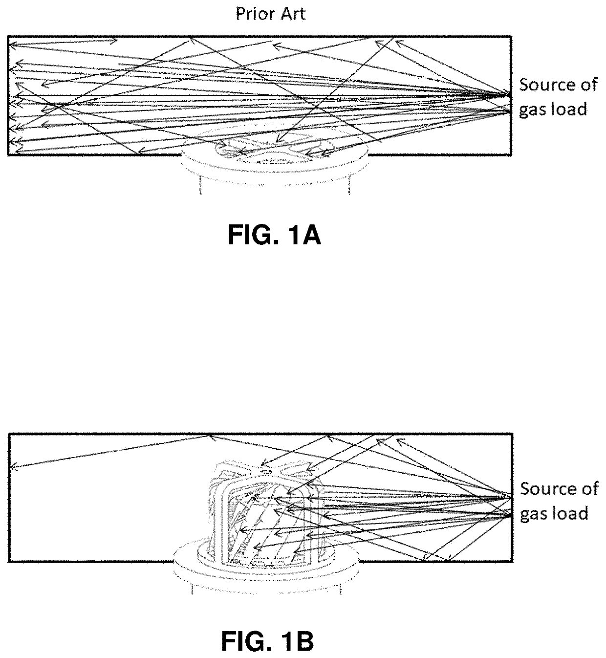
[0072]The basic idea of the invention is to increase pumping speed by increasing the rotor blade cross section exposed to the chamber to be evacuated. This increases the probability of molecules to hit the rotor blades at high to ultra-high vacuum. This objective can be achieved by providing a rotor blade assembly of cage-like configuration, preferably fully exposed to the vacuum chamber, see concept illustrated schematically in FIG. 1B. The cage-like rotor blade assembly encompasses paraxially arranged rotor blade portions along the circumference of the notional “cage”. In addition, it may encompass one or more sets of radial rotor blade portions for holding the paraxial rotor b...


PUM

PropertyMeasurementUnit
pressuresaaaaaaaaaa
pressuresaaaaaaaaaa
atmospheric pressureaaaaaaaaaa

Abstract

The invention relates to turbo molecular pumps enabling high pumping speed. The disclosure suggests using one or more cage-like rotor stages to optimize pumping speed on vacuum systems with low gas flows and low ultimate pressures. This allows for a smaller motor as well as smaller overall form factor and makes it well suited, in particular, for compact mass spectrometers and desk-top mass spectrometers.

Description

BACKGROUND OF THE INVENTIONField of the Invention[0001]The invention relates to turbo molecular pumps enabling high pumping speed.Description of the Related Art[0002]A conventional turbo molecular pump typically consists of a low pressure input stage and a high pressure exhaust section. The low pressure input stage consists of a stack of rotors, each with multiple, angled blades which rotate at very high tangential speed mounted in a tube-like housing. Gas molecules, hit by the underside of the angled blades, move with momentum in the direction of the higher pressure exhaust section.[0003]The low pressure input stage thus consists of stacks of discoidal turbo rotors with radially extending rotor blades. Usually there are non-rotating stators with oppositely angled radial blades between each of the rotors. The pumping speed of a turbo molecular pump is given by the blade diameter and the rotational speed (in rotations per minute, RPM) of the turbo rotor blades. The rotational speed i...

Claims


Application Information

Patent Timeline
Patent Type & Authority Patents(United States)
IPC IPC(8): H01J49/04F04D19/04H01J49/24H01J49/26F04D29/38F04D17/02F04D25/12
CPCH01J49/0422F04D17/02F04D17/025F04D19/042F04D25/12F04D29/384H01J49/24F05D2300/121F05D2300/125F05D2300/133H01J49/26F04D29/32F04D29/522F04D29/284F04D29/321F04D25/16B33Y80/00B22F5/04F04D29/26
Inventor STEINER, URSFRANZEN, JOCHEN
Owner BRUKER DALTONIK GMBH & CO KG
Why Eureka
Try Eureka