
Method and system for determining a risk of hemodynamic compromise after cardiac intervention

a risk and cardiac intervention technology, applied in the field of preoperative planning of transcatheter structural heart interventions, can solve the problems of hemodynamic compromise, hemodynamic compromise, obstruction of coronary arteries, etc., and achieve the effect of reliable measurement of obstruction

Active Publication Date: 2021-06-29
FEOPS NV
View PDF19 Cites 4 Cited by
  • Summary
  • Abstract
  • Description
  • Claims
  • Application Information

AI Technical Summary

Benefits of technology

The patent describes a method for predicting the risk of complications such as obstruction and leakage when treating cardiac valves using valve replacement or repair procedures. The method involves creating a patient-specific anatomical model of the heart and predicting the measure of hemodynamic compromise, such as the cross-sectional area of blood flow paths, before and after the procedure. This allows a physician to determine the minimum and maximum values of the hemodynamic compromise and select an implant model with the least risk of causing complications. The method can also include virtually deploying different implant models into the patient-specific anatomical model to compare their risk of hemodynamic problems and select the most suitable implant model for the procedure. Overall, the method provides a way to predict the risk of hemodynamic complications and optimize the treatment plan for cardiac valve disease.

Problems solved by technology

TAVI may lead to an obstruction of the coronary arteries, due to the movement of the calcified native leaflets towards the coronary ostia, or due to the presence of the TAV itself.
Thus, transcatheter cardiac valve implantation / replacement or repair can lead to hemodynamic compromise.
The hemodynamic compromise can be obstruction of a primary blood flow path in which the valve is implanted.
Such obstruction can cause a drop (gradient) in blood pressure over the implanted device.
The hemodynamic compromise can be obstruction of a secondary blood flow path in communication with the primary blood flow path, e.g. at the location of the implanted device.

Method used


Image

  • Method and system for determining a risk of hemodynamic compromise after cardiac intervention
  • Method and system for determining a risk of hemodynamic compromise after cardiac intervention
  • Method and system for determining a risk of hemodynamic compromise after cardiac intervention

Examples


Embodiment Construction

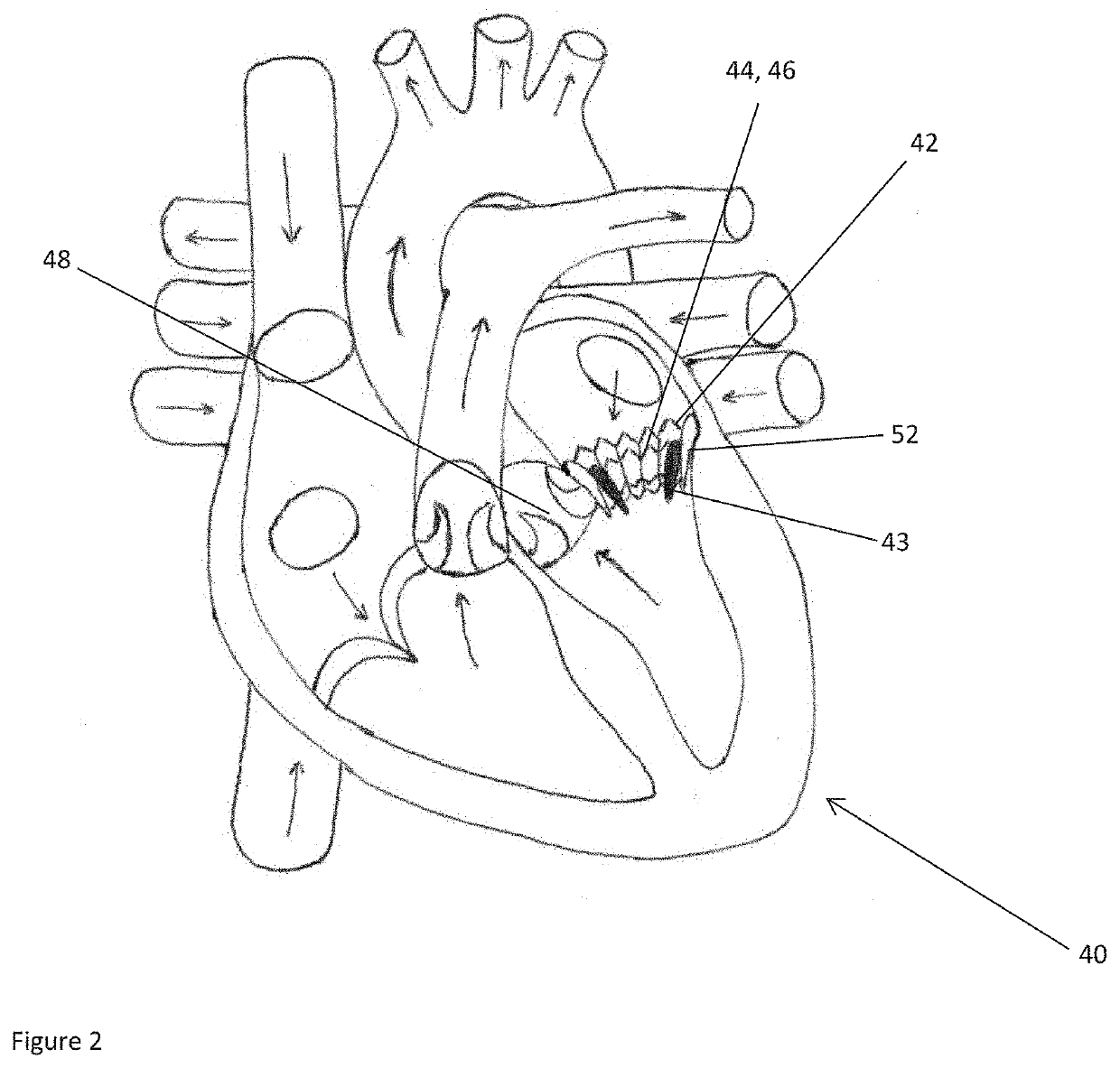
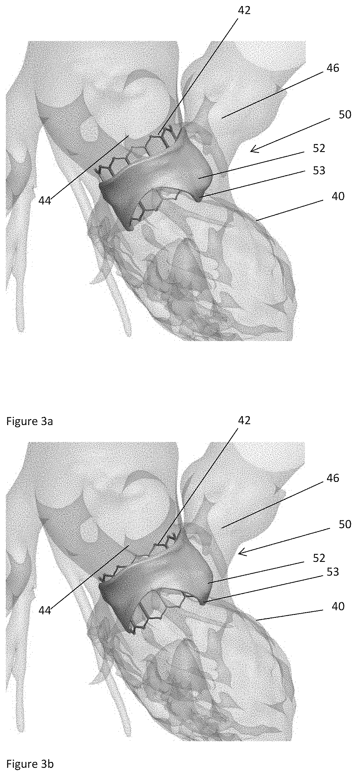
[0051]Left ventricular outflow tract (LVOT) obstruction after a transcatheter mitral valve replacement (TMVR) procedure is a frequent complication. LVOT obstruction after TMVR in patients with mitral annular calcification may occur in approximately 10% of the patients. This can result in increased mortality after one year. Using the present technology, however, a predictor for the occurrence of LVOT obstruction or other hemodynamic compromise can be given.

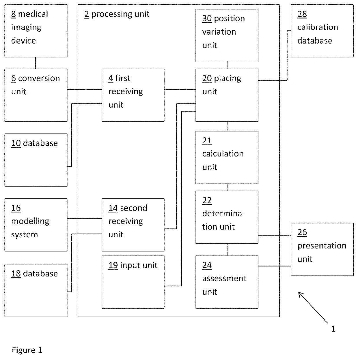
[0052]FIG. 1 shows a schematic example of a system 1 for predicting a measure of hemodynamic compromise, such as obstruction of a blood flow path, as a result of transcatheter cardiac valve treatment. The system includes a processing unit 2. The processing unit 2 includes a first receiving unit 4 for receiving a patient-specific anatomical model. Here the patient-specific anatomical model represents a patient-specific cardiac valve region.

[0053]In this example, the patient-specific anatomical model is provided as a three dimensiona...


PUM


Abstract

A method and system for predicting a measure of hemodynamic compromise as a result of transcatheter cardiac treatment. The method includes providing a patient-specific anatomical model representing cardiac region and an implant model representing a three-dimensional representation of a cardiac implant. The method includes virtually deploying said implant model into said patient-specific anatomical model. A deformation of the patient-specific anatomical model is calculated as a result of implant model deployment A measure of hemodynamic compromise is determined from the virtually deployed implant model and the deformed patient-specific anatomical model.

Description

[0001]This application claims priority from International Application No. PCT / EP2018 / 052701, filed on Feb. 2, 2018, which claims priority from European patent application numbers EP 17154648.4, filed on Feb. 3, 2017, both of which are incorporated herein in their entirety.FIELD OF THE INVENTION[0002]The present invention relates to the field of pre-operative planning of transcatheter structural heart interventions, e.g. valve treatment, such as valve implantation and / or repair. More in particular, the invention relates to pre-operative prediction of the risk a patient developing hemodynamic compromise as a result of transcatheter valve treatment.BACKGROUND TO THE INVENTION[0003]The left ventricle of the heart pumps the blood to the aorta through the aortic valve. Aortic (valve) stenosis is a pathology occurring when the aortic valve does not open fully because the leaflets calcify, thicken and stiffen and, as a result, the blood flow going from the heart to the systemic circulation ...

Claims


Application Information

Patent Timeline
Patent Type & Authority Patents(United States)
IPC IPC(8): A61B34/10G16H20/40G16H50/50G16H30/20A61B5/021A61B5/026
CPCA61B34/10A61B5/021A61B5/026G16H20/40G16H30/20G16H50/50A61B2034/102A61B2034/105A61F2/2412A61B2034/104A61B2034/101
Inventor MORTIER, PETER EDDY J.DEBUSSCHERE, NICDE SANTIS, GIANLUCADEZUTTER, TIMDE BEULE, MATTHIEU ROBERT ANNA FIRMIN
Owner FEOPS NV
Learn More