Magnetic recording head with non-magnetic conductive structure surrounding a main pole and contacting a spin torque oscillator

a magnetic recording head and non-magnetic conductive technology, applied in the field of magnetic recording heads, can solve the problems of reducing the reliability of the data storage device, low current efficiency from the main pole to the sto, etc., and achieve the effect of high current density, maximum current efficiency and uniformity

Active Publication Date: 2021-06-29
WESTERN DIGITAL TECH INC
View PDF54 Cites 6 Cited by
  • Summary
  • Abstract
  • Description
  • Claims
  • Application Information

AI Technical Summary

Benefits of technology

[0005]The present disclosure generally relates to data storage devices, and more specifically, to a magnetic media drive employing a magnetic recording head. The head includes a trailing shield, a main pole, an STO disposed between the trailing shield and the main pole, and a non-magnetic conductive structure (or non-magnetic conductive layers) adjacent to the main pole and in contact with the STO. The non-magnetic conductive structure provides additional paths for electrical currents to flow to the STO. The non-magnetic conductive structure enables higher current density to the STO without creating hot spots at the MFS. Maximum current efficiency and uniformity can be achieved with the non-magnetic conductive structure.

Problems solved by technology

However, current efficiency from the main pole to the STO is low due to current crowding.
Furthermore, hot spots can form at a media facing surface (MFS) when higher current density is driven to the STO, reducing the reliability of the data storage device.

Method used


Image

  • Magnetic recording head with non-magnetic conductive structure surrounding a main pole and contacting a spin torque oscillator
  • Magnetic recording head with non-magnetic conductive structure surrounding a main pole and contacting a spin torque oscillator
  • Magnetic recording head with non-magnetic conductive structure surrounding a main pole and contacting a spin torque oscillator

Examples


Embodiment Construction

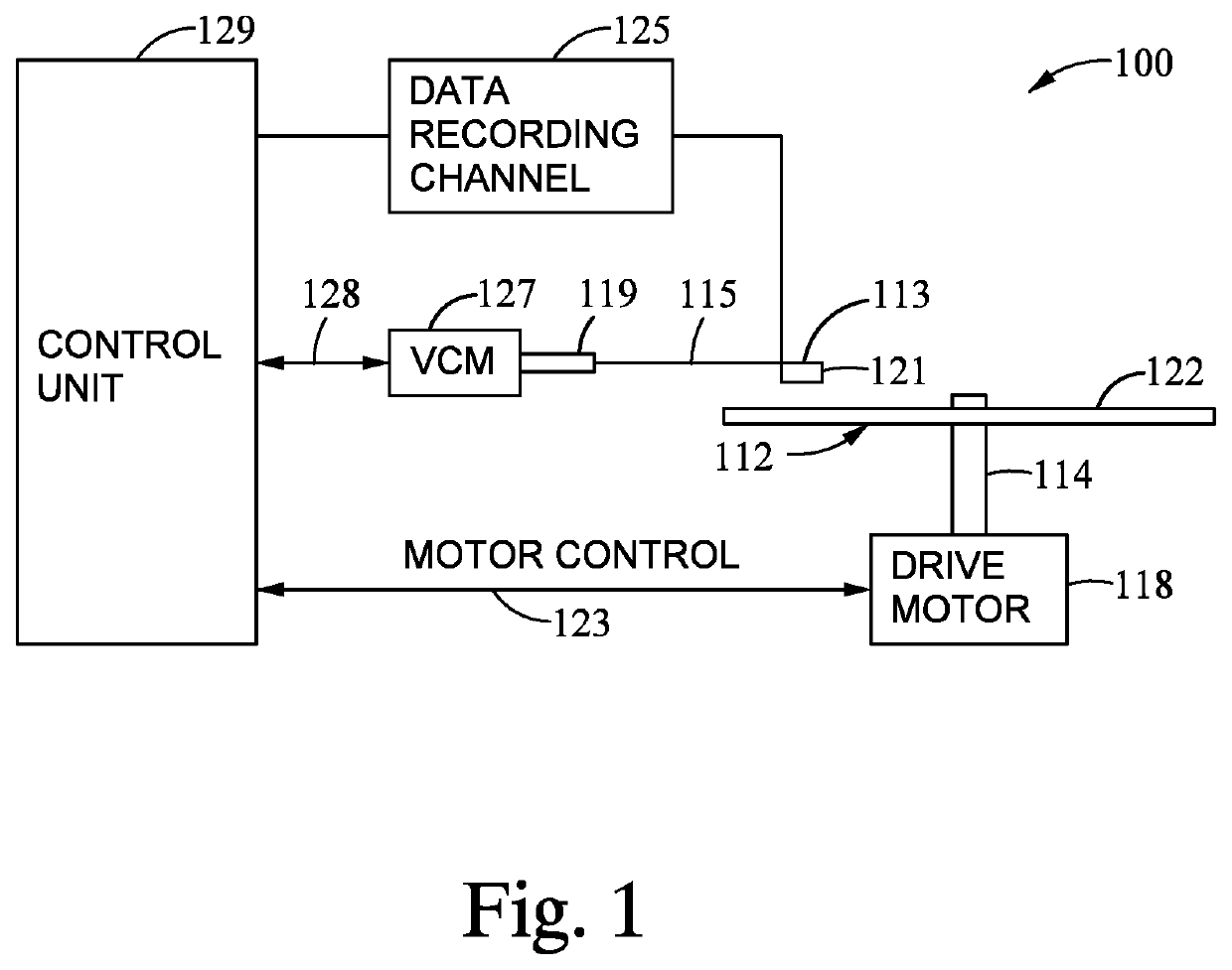
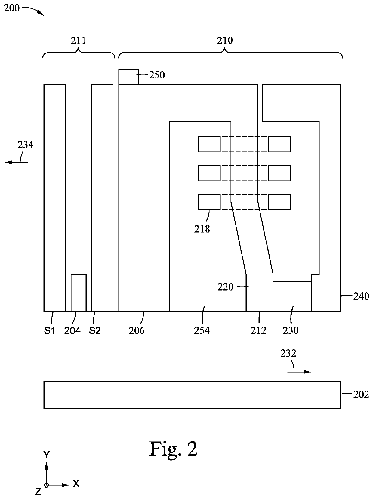
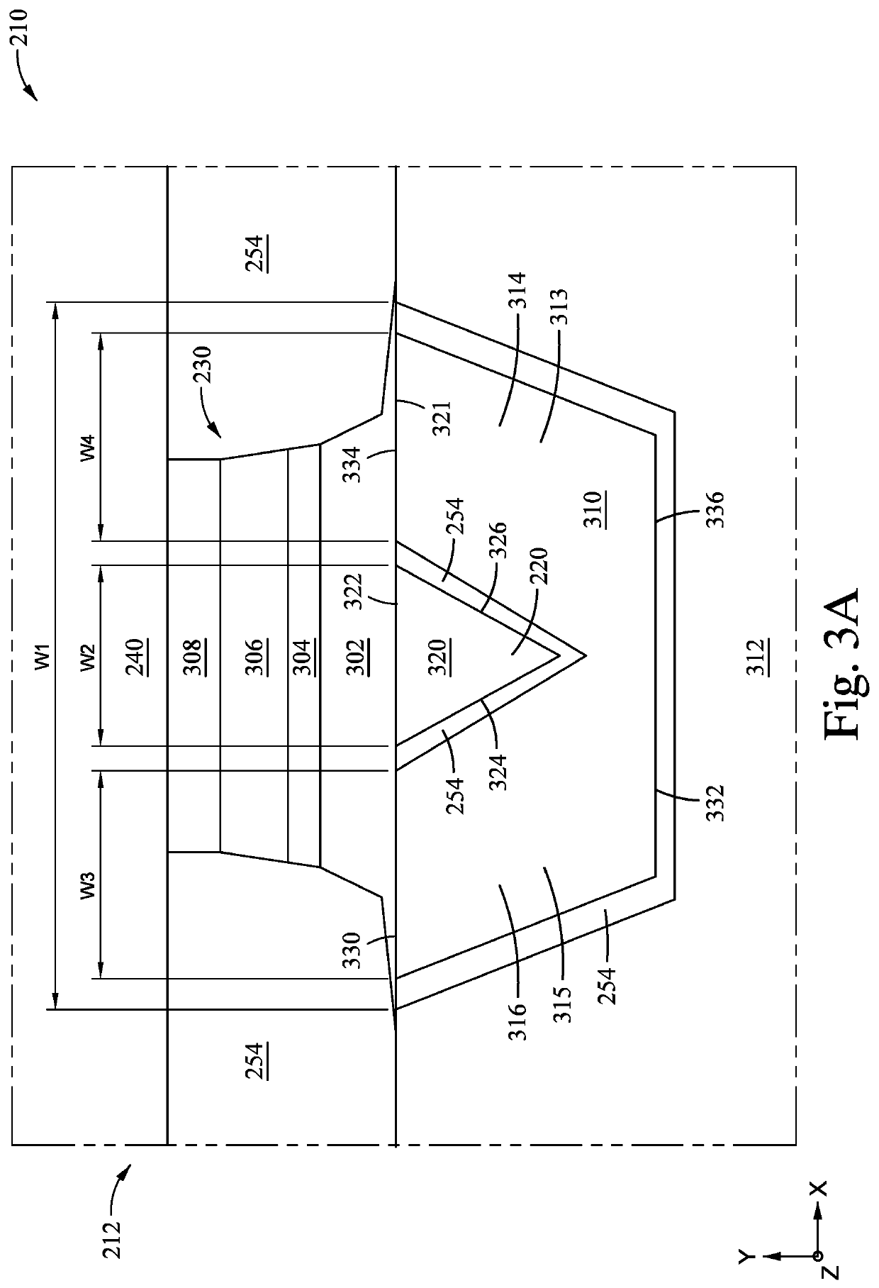
[0021]The present disclosure generally relates to data storage devices, and more specifically, to a magnetic media drive employing a magnetic recording head. The head includes a trailing shield, a main pole, an STO disposed between the trailing shield and the main pole, and a non-magnetic conductive structure (or non-magnetic conductive layers) adjacent to the main pole and in contact with the STO. The non-magnetic conductive structure provides additional paths for electrical currents to flow to the STO. The non-magnetic conductive structure enables higher current density to the STO without creating hot spots at the MFS. Maximum current efficiency and uniformity can be achieved with the non-magnetic conductive structure.

[0022]The terms “over,”“under,”“between,” and “on” as used herein refer to a relative position of one layer with respect to other layers. As such, for example, one layer disposed over or under another layer may be directly in contact with the other layer or may have ...


PUM

PropertyMeasurementUnit
widthaaaaaaaaaa
non-magnetic conductiveaaaaaaaaaa
conductiveaaaaaaaaaa

Abstract

The present disclosure generally relates to data storage devices, and more specifically, to a magnetic media drive employing a magnetic recording head. The head includes a trailing shield, a main pole, an STO disposed between the trailing shield and the main pole, and a non-magnetic conductive structure (or non-magnetic conductive layers) adjacent to the main pole and in contact with the STO. The non-magnetic conductive structure provides additional paths for electrical currents to flow to the STO. The non-magnetic conductive structure enables higher current density to the STO without creating hot spots at the MFS. Maximum current efficiency and uniformity can be achieved with the non-magnetic conductive structure.

Description

CROSS-REFERENCE TO RELATED APPLICATIONS[0001]This application claims benefit of U.S. Provisional Patent Application Ser. No. 62 / 824,819, filed Mar. 27, 2019, which is herein incorporated by reference.BACKGROUNDField of the Disclosure[0002]Embodiments of the present disclosure generally relate to data storage devices, and more specifically, to a magnetic media drive employing a magnetic recording head.Description of the Related Art[0003]Over the past few years, microwave assisted magnetic recording (MAMR) has been studied as a recording method to improve the areal density of a magnetic read / write device, such as a hard disk drive (HDD). MAMR enabled magnetic recording heads utilize a spin torque oscillator (STO) for generating a microwave (high frequency AC magnetic field). When the magnetic field from the write head is applied and current is conducted to the STO from the main pole, the STO oscillates and may provide an AC magnetic field to the recording medium. The AC magnetic field...

Claims


Application Information

Patent Timeline
Patent Type & Authority Patents(United States)
IPC IPC(8): G11B5/235G11B5/31G11B5/127G11B5/39G11B5/00
CPCG11B5/235G11B5/1278G11B5/314G11B5/3143G11B5/3146G11B5/3163G11B5/315G11B5/3903G11B2005/0024
Inventor LE, QUANGHO, KUOK SANSONG, SUPINGBAIAO DE ALBUQUERQUE, GONCALO
Owner WESTERN DIGITAL TECH INC
Why Eureka
Try Eureka