Feedthrough with flat conductor

a technology of conductor and feed tube, which is applied in the direction of cell components, hermetically sealed casings, electric apparatus casings/cabinets/drawers, etc., can solve the problems of only insufficient enlargement of available connecting surfaces and no production specifications as to how many openings, etc., to reduce assembly space, minimize component height, and large connecting surfaces

Active Publication Date: 2021-07-20
SCHOTT AG
View PDF26 Cites 1 Cited by
  • Summary
  • Abstract
  • Description
  • Claims
  • Application Information

AI Technical Summary

Benefits of technology

[0017]In some exemplary embodiments, the cross section of the round conductor is in the range of 10 mm2 to 20 mm2, such as 12 mm2 to 14 mm2, or 13 mm2. The round conductor is formed due to reshaping, which may comprise squeezing, such as by a preceding head compression, in such a way that the rectangular cross section of the part of the flat conductor has a thickness in the range of 1 mm to 3 mm, such as 1.5 mm, and a width in the range of 5 mm to 20 mm, such as 10 mm. The length of the squeezed area or respectively the length of the squeeze QL is in a range of 2 to 8 mm, such as 7.5 mm. The surface of the flat conductor, resulting from B·D has a surface area of 15 mm2, which is approximately consistent with the cross section of the round conductor. In some exemplary embodiments, the cross sectional surface area of the round cross section of the conductor is substantially consistent with the cross sectional surface area of the rectangular cross section of the part and / or region of the flat conductor and / or the cumulative flat conductor above and / or below the glazing. This ensures that no losses and / or contact resistance occur during operation due to a change in the conductor cross section.
[0018]In regard to the glazing, exemplary embodiments formed in accordance with the present disclosure provide that the conductor in the region of the glazing has a substantially round cross section. This makes it possible to actualize the glazing as a compression seal. This term is known to one skilled in the art. Essentially, it means that the thermal coefficient of expansion of the housing material into which the glazing occurs is greater than the thermal coefficient of expansion of the sealing material. Thus, after glazing, the housing material exerts pressure upon the glazing and thereby also upon the conductor to achieve a hermetically sealed and permanently mechanically reliable feedthrough.
[0020]In some exemplary embodiments, the overall width or overall width expansion of the cumulative flat conductor during merging of, for example, three individual flat conductors is in the range of 15 to 60 mm, such as 30 mm. The resulting surface area for the cumulative flat conductor, determined by thickness times width, is in the range of 22.5 to 90 mm2, such as around 45 mm2. In the case of three round conductors with a cross sectional surface of 13 mm2 each, the cross sectional surface area of the three round conductors is substantially consistent with the cross sectional surface area of the cumulative flat conductor, consisting of three individual flat conductors, so that conductive losses due to cross sectional constrictions are avoided. According to the present disclosure, the diameter of the opening (DO) into which the conductor is glazed is smaller than the width (B, DF) of the rectangular regions of the respective part of the flat conductor. The rectangular region has a width B and a thickness D so that the surface of the rectangular region is B·D. As used herein, the width is also referred to as “maximum expansion.”
[0030]In some exemplary embodiments, only a small space exists between the cumulative flat conductor, which results from the composition of a multitude of parts of flat conductors into a cumulative conductor, and the surface of a housing part in which the openings through which the conductor having the round cross section is fed. The space may be 0.5 to 10 mm, such as 1 to 10 mm, 2 to 10 mm or 1 to 5 mm, or 2 to 5 mm. The space may be an air gap. It was surprisingly found that such a small distance from the reshaped cumulative flat conductor to the surface and glazing is possible. It was not foreseeable that a sufficiently large connecting surface could be produced by strong reshaping near the glazing, without damaging the glazing. The transition area from round to angular is very short, and the transition area does not extend into the glazing area during reshaping. It was surprising that the reshaping process is so precisely controllable. Due to the small distance of the cumulative flat conductor from the surface, the air gap can be held small, thereby minimizing the component height. The necessary assembly space is thereby reduced and in the use, for example, in batteries a contribution toward increasing cell capacity is provided, since with the same overall assembly space, more space is available for the cells and the connecting technology requires less assembly height.
[0031]An additional surprising characteristic is that such strong reshaping can occur that the individual regions can be joined into a single flat conductor without additional material becoming necessary for filling of the gaps. This facilitates efficient production.

Problems solved by technology

The terminal lugs known from the current state of the art enlarge the available connecting surface only insufficiently.
Moreover, no production specifications are provided as to how many openings are required in order to provide a wide connecting conductor.

Method used


Image

  • Feedthrough with flat conductor
  • Feedthrough with flat conductor
  • Feedthrough with flat conductor

Examples


Embodiment Construction

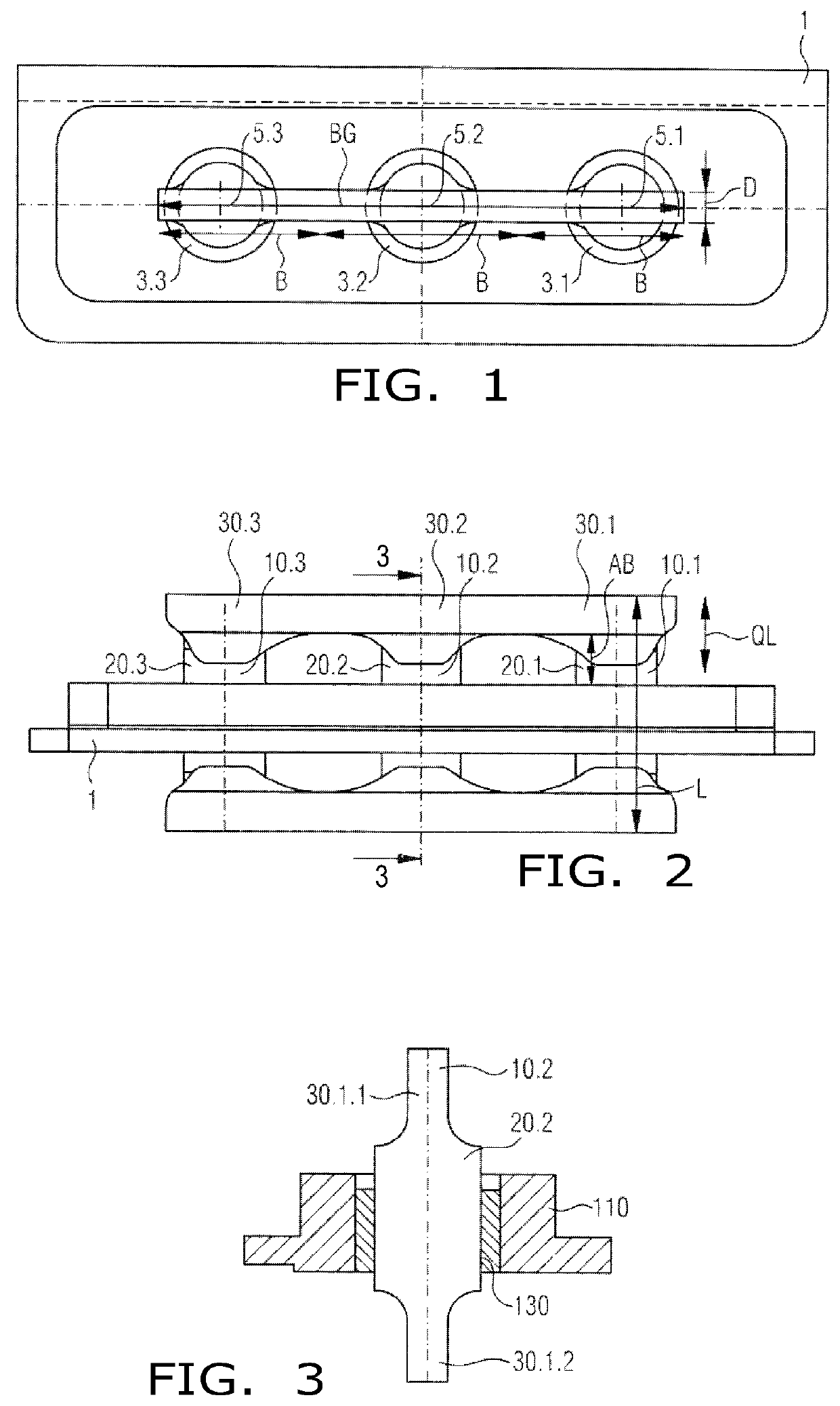
[0057]FIG. 1 shows a top view of an exemplary embodiment of a feedthrough formed according to the present disclosure through a housing part of a housing that may consist of a light metal, such as aluminum or an aluminum alloy, AlSiC, magnesium, a magnesium alloy, titanium, or a titanium alloy.

[0058]The housing part is identified with reference number 1 and, in the illustrated embodiment, includes three openings 3.1, 3.2, 3.3 into which a conductor—which is not shown from above in the top view—is sealed. In the embodiment illustrated in FIG. 1, glazing occurs into a base body, which in turn is inserted into the openings 3.1, 3.2, 3.3 of the housing part 1 and fused with same. Round conductor sections are inserted and glazed into the total of three openings 3.1, 3.2, 3.3 since glazing of round conductors provides a hermetically sealed feedthrough that has a helium leakage rate of less than 10−8 mbarl s−1 at a pressure differential of 1 bar. The conductors having a round cross section ...


PUM

PropertyMeasurementUnit
lengthaaaaaaaaaa
surface areaaaaaaaaaaa
lengthaaaaaaaaaa

Abstract

A feedthrough assembly includes a housing part having at least two openings, respectively through which at least one conductor embedded in a glass or a glass ceramic material is fed. The conductor, in the region of a glazing area, has a substantially round cross section, and in a first and / or second region above and / or below the glazing area has a substantially rectangular cross section to form a part of a flat conductor having rectangular regions. The parts of the flat conductor arranged above and / or below the glazing area are joined adjacent to one another, resulting in a cumulative flat conductor having a rectangular common cross section with a total width expansion that extends over the at least two openings. The diameter of the openings is smaller than a width of the rectangular regions of the respective part of the flat conductor.

Description

BACKGROUND OF THE INVENTION1. Field of the Invention[0001]The present disclosure relates to a feedthrough with a flat conductor, such as through a housing part of a housing, which may be constructed of light metal, such as aluminum or an aluminum alloy, AlSiC, magnesium, a magnesium alloy, titanium, a titanium alloy. The housing part has at least two openings, respectively through which at least one conductor that is embedded in a glass or a glass ceramic material is fed, as well as a process for the manufacture of same and use of same.2. Description of the Related Art[0002]Feed-throughs through housing parts in housings which consist of a light material, in particular of aluminum or an aluminum alloy have become known from a plurality of patent applications. WO 2012 / 110 242 A1, for example, discloses a feedthrough, in particular through a housing part of a housing, wherein substantially pin-type conductors are glazed into a base body and wherein the base body is introduced into an ...

Claims


Application Information

Patent Timeline
Patent Type & Authority Patents(United States)
IPC IPC(8): H05K5/00H05K5/02H05K5/06H01R11/01H01G2/10H05K5/04H01M50/172
CPCH05K5/0247H01R11/01H05K5/069H01G2/103H01M50/172H05K5/04H01G11/74H01G11/80Y02E60/10H01M50/186H01M50/191H01G4/236B23K31/02H01B1/02B23K2101/38B23K2103/52
Inventor HARTL, HELMUT
Owner SCHOTT AG
Why Eureka
Try Eureka