Nanoparticle production

a nanoparticle and nanotechnology, applied in the field of nanoparticle production, can solve the problems of controlling the foaming caused by hydrogen gas production in the reactor, and achieve the effect of stabilising the nanoparticle make-up and reducing the environmen

Active Publication Date: 2021-08-17
MIDATECH LTD +1
View PDF13 Cites 0 Cited by
  • Summary
  • Abstract
  • Description
  • Claims
  • Application Information

AI Technical Summary

Benefits of technology

[0010]Broadly, the present invention relates to nanoparticle production methods in which a solution comprising nanoparticle reactants (e.g. metal salts and derivatised ligands) are added dropwise to a solution containing a reducing agent (e.g. sodium borohydride). The relatively small size of the droplets containing the nanoparticle reactants tends to ensure rapid mixing and consequently increasingly uniform properties of the nanoparticles produced (such as tighter size distribution). The solution containing the nanoparticle reactants may conveniently be ejected as droplets from a droplet generator to pass through a gas into the solution containing the reducing agent. The solution containing the reducing agent may be provided in the form of a continuously-stirred pool of liquid in a vessel or in the form of a liquid stream (e.g. in a channel or as a jet of the liquid passing through a gas). The present inventors have surprisingly found that nanoparticles produced in this way exhibit good uniformity. Moreover, this method of producing nanoparticles is more amenable to scale-up, not least because constraints imposed by previously known methods of production (e.g. rate of mixing of the reducing agent and changes in reducing agent concentration over time) are largely avoided by the production method of the present invention.
[0041]The second liquid may be provided in any configuration that permits the droplets of the first liquid, after being dispensed from the liquid droplet generator(s) and passing through a gas, to enter or make contact with a surface of the second liquid. In certain cases, the second liquid may be provided in an open-topped vessel, a thin film, or a spinning disc reactor. In certain cases, the vessel may be a stirred flask or bath. Stirring facilitates distribution of the reducing agent and helps to maintain a uniform concentration of the reducing agent in the second liquid. This helps to prevent local areas of lowered reducing agent concentration at the site of entry of the liquid droplets of the first liquid.
[0044]A particular advantage of providing the second liquid as a flow in a channel or as a jet is that the concentration of the reducing agent can readily be maintained at a constant level. When the nanoparticle reactants (metal salt and ligands) are added to a vessel containing reducing agent at a particular concentration, the reducing agent concentration will deplete with time as more and more droplets of the first liquid are added. This will not be the case where the second liquid is provided as a flow or jet because the concentration of reducing agent in the second liquid at the site of initial contact of the droplets of the first liquid will be constant over time. This in turn helps to ensure consistency of properties (e.g. size) within a production batch. In some cases, the jet approach ensures constant reaction conditions with no meaningful concentration depletions in either the first or second liquids.
[0054]In some cases, the further added ligands are the same as the at least one species of ligand in the first liquid. In this way subsequent ligand binding to uncapped core surface atoms or competitive displacement of existing ligands tends to result in addition of “more of the same” or like-for-like ligand replacement, and thereby stabilises the nanoparticle make-up (shifting from meta-stable to fully stable).

Problems solved by technology

A particular problem with the aforementioned synthesis method (e.g. described in WO 02 / 32404) is that uniformity of the resultant nanoparticle properties (including size) depends in large part on achieving near instantaneous mixing of the added sodium borohydride with the gold salt and thiol-derivatised ligands.
Moreover, the sodium borohydride is a source of potentially flammable hydrogen gas, which therefore necessitates carefully controlled conditions, especially for larger-scale reaction methods.
Controlling foaming caused by hydrogen gas production within the reactor is a problem.

Method used


Image

  • Nanoparticle production
  • Nanoparticle production
  • Nanoparticle production

Examples


example

Example 1—Piezoelectric Ejection-Based Synthesis of Gold Nanoparticles

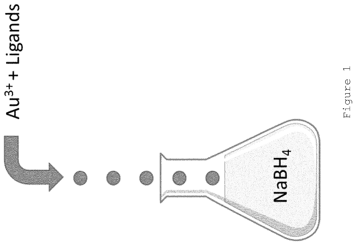
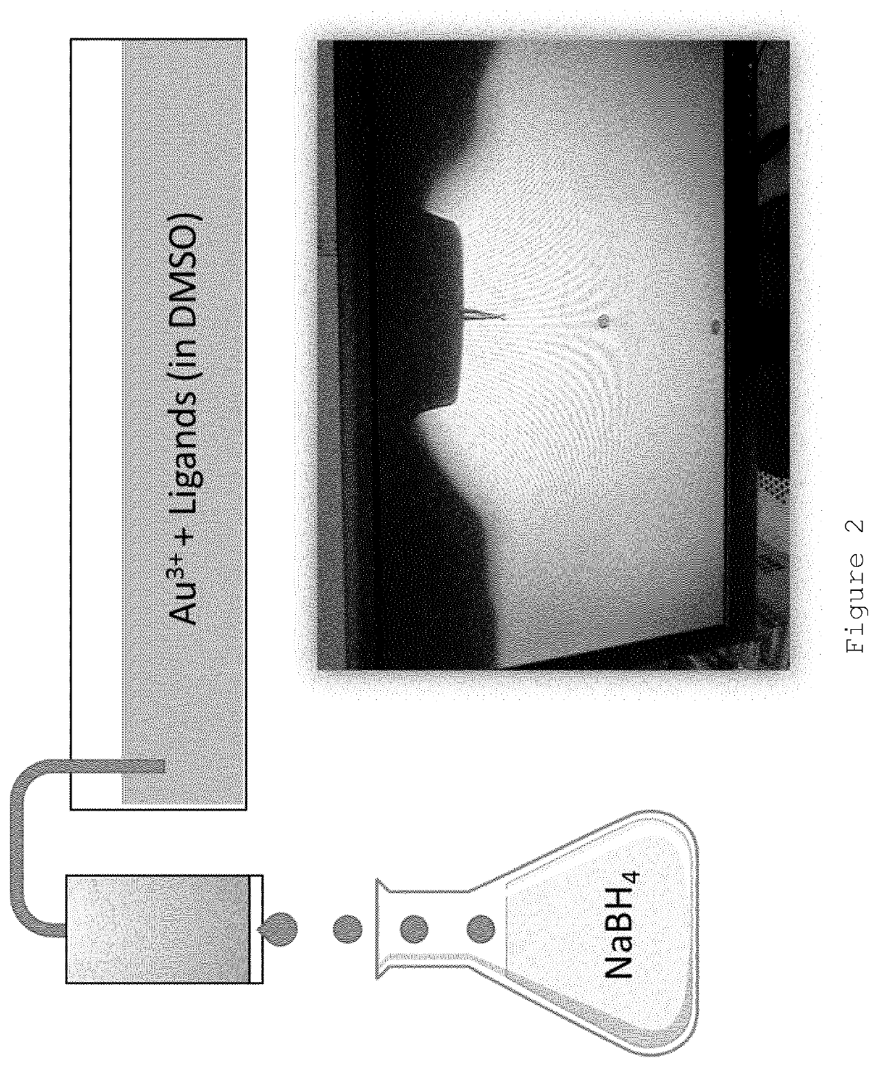
[0081]A solution containing HAuCl4 ([Au3+] of 1 mg / ml), glucose-C2-disulphide (Au3+: Glucose-C2-disulphide 1:3 mole ratio) in DMSO was ejected from a single piezoelectric droplet generator using the following ejection conditions: 44V, 13 μs pulse, 50° C., n=4000 Hz. The droplets were ejected into a 12 mL vial containing 8 mL of an aqueous solution of NaBH4 at a concentration of 0.05M.

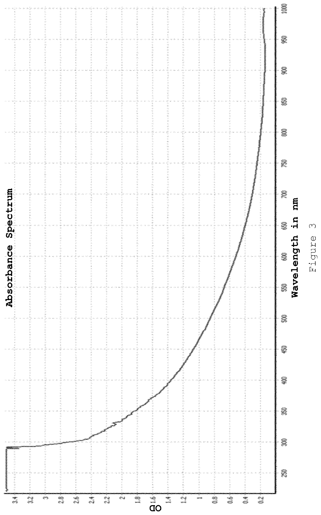
[0082]The resulting nanoparticles were isolated by Amicon ultracentrifugation after droplet ejection was complete. Meta-stable nanoparticles of appropriate size were produced (demonstrated by a very small plasmon band). It was found that these nanoparticles “ripened” overnight with the size increasing to a diameter of >8 nm (red colour observed). The present inventors believe that this indicates that the gold nanoparticle core was not fully capped with ligand at the point when the nanoparticles were isolated (i.e. the nanoparticles we...


PUM

PropertyMeasurementUnit
frequencyaaaaaaaaaa
droplet volumeaaaaaaaaaa
concentrationaaaaaaaaaa

Abstract

The present invention provides a process for producing nanoparticles, comprising: providing a first liquid comprising a metal salt and at least one species of ligand having a functional group capable of binding to a metal surface, providing a second liquid comprising a reducing agent; providing at least one liquid droplet generator operable to generate liquid droplets, causing the at least one liquid droplet generator to form liquid droplets of the first liquid, passing the liquid droplets through a gas to contact the second liquid so as to cause the metal salt and the at least one species of ligand to come into contact with the reducing agent, thereby causing self-assembly of nanoparticles, said nanoparticles having a core of said metal and a corona comprising a plurality of said ligands covalently bound to the core. Also provided are nanoparticles produced by the process of the invention and use of such nanoparticles in medicine.

Description

FIELD OF THE INVENTION[0001]The present invention relates to processes for the production of nanoparticles, particularly nanoparticles having a metal or semiconductor core, which core is covalently bound by a plurality of ligands. The nanoparticles may have one or more payloads covalently or non-covalently bound thereto, for example acting as pharmaceutical carriers.BACKGROUND TO THE INVENTION[0002]The present invention is directed at methods for the production of nanoparticles. Nanoparticles for use in medical and diagnostic applications, and methods for their production are known. WO 02 / 32404 describes the synthesis and characterisation of gold nanoparticles functionalised with thiol derivatised carbohydrate ligands (glyconanoparticles). A solution of the ligands (in disulphide form) in methanol was added to a solution of tetrachloroauric acid in water. Sodium borohydride in water was added in small portions with rapid stirring to the vessel containing the ligands and gold salt. A...

Claims


Application Information

Patent Timeline
Patent Type & Authority Patents(United States)
IPC IPC(8): B01J13/04B01J13/02A61K47/69
CPCB01J13/04A61K47/6923A61K47/6929B01J13/02A61P35/00A61K9/5192A61K49/0093
Inventor PALMER, DANIELGROVES, RHIANSEAMAN, PAULCAVALIER-HIRTH, VICTORIAPACE, ALESSANDRO
Owner MIDATECH LTD
Why Eureka
Try Eureka