
OLED display machine with illumination function

a technology of light-emitting diodes and display machines, which is applied in the field of display devices, can solve the problems of lack of versatility, inability to meet the needs of the market, and lack of functions, and achieves the effects of increasing brightness, enhancing illumination effect, and increasing illumination area

Active Publication Date: 2021-08-24
WUHAN CHINA STAR OPTOELECTRONICS TECH CO LTD
View PDF9 Cites 0 Cited by
  • Summary
  • Abstract
  • Description
  • Claims
  • Application Information

AI Technical Summary

Benefits of technology

The present invention is for an organic light-emitting illumination device that does not have a color resist layer or pixel defining layer. This allows the device to have a larger illuminating area, resulting in a brighter white light. The device is also easy to control and operate using a TFT device. The technical effect is high-brightness illumination and simple operation.

Problems solved by technology

The existing OLED displays have display functions but have no illumination functions, so they fail to provide plenty of functions, lack versatility, and cannot meet the needs of the market.

Method used


Image

  • OLED display machine with illumination function
  • OLED display machine with illumination function
  • OLED display machine with illumination function

Examples


first embodiment

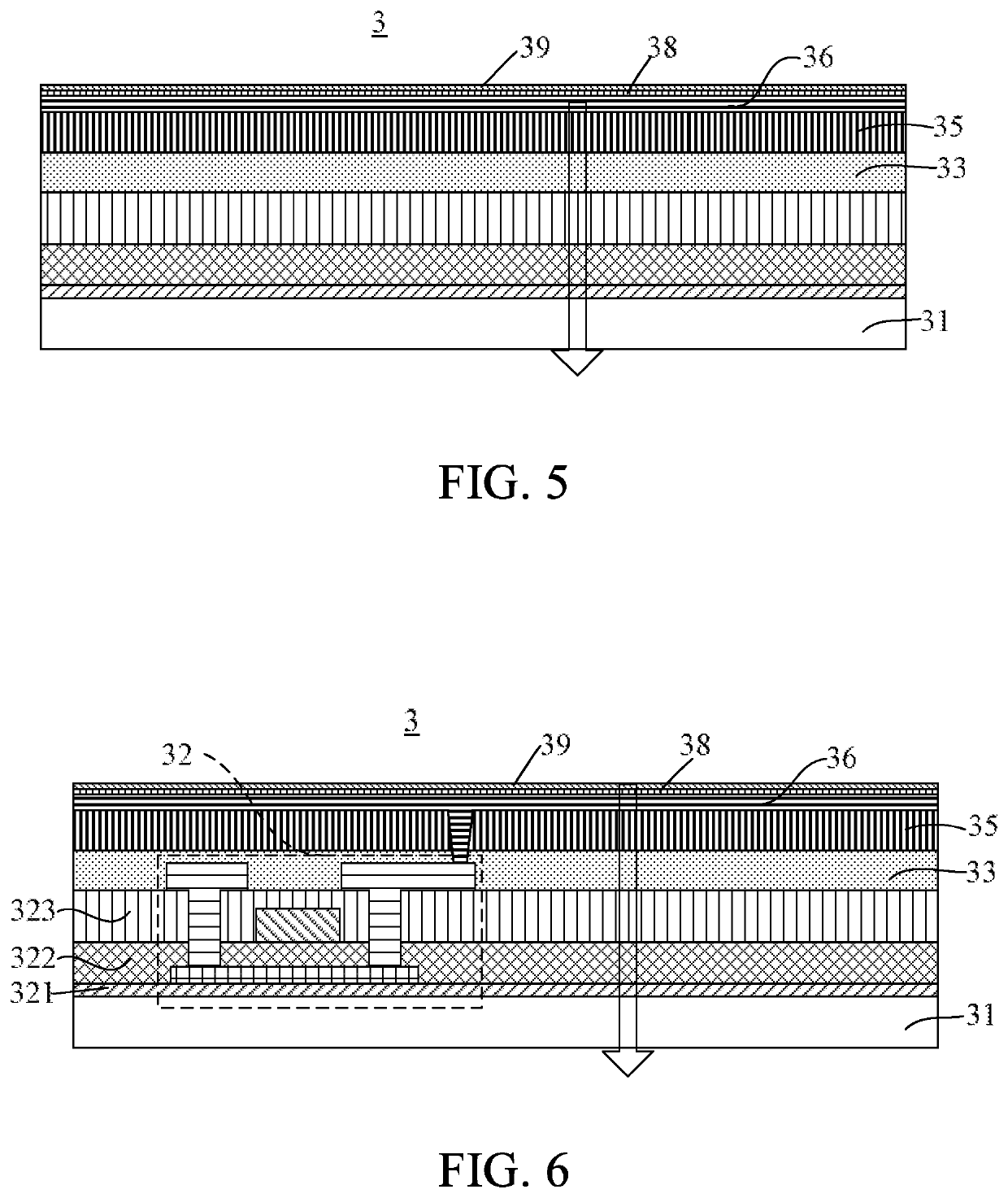
[0043]Please refer to FIG. 5, which is a cross-sectional view illustrating an organic light-emitting illumination device according to the present invention. The organic light-emitting illumination device 3 comprises a substrate 31, an insulating layer 33, a planarization layer 35, an anode electrode 36, a light-emitting material layer 38, and a cathode electrode 39. A drive circuit is electrically connected to the anode electrode 36 and the cathode electrode 39 of the organic light-emitting illumination device 3 to control an ON or OFF state of the organic light-emitting illumination device 3. Therefore, the OLED display machine provides not only a display function but also illumination, which facilitate wide application and development of the OLED display machine 1.

second embodiment

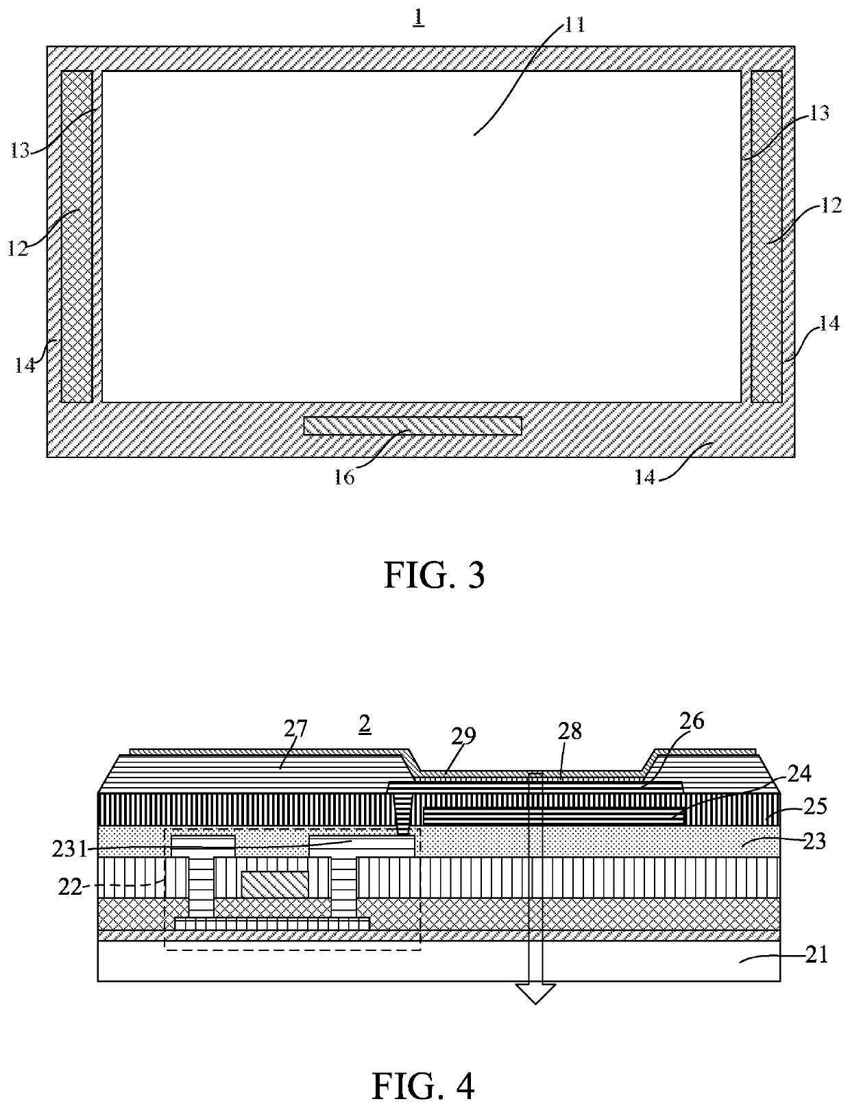
[0044]In detail, the drive circuit is, for example, a bonding terminal 16 for being connected to an external signal. The bonding terminal 16 is disposed at, for example, the lower one of the side edges 14 in FIG. 3 and is electrically connected to the anode electrode 36 and the cathode electrode 39, thereby providing a drive signal to supply power to the light-emitting material layer 38 and controlling the ON or OFF state of the organic light-emitting illumination device 3. However, shown in FIG. 6, a thin film transistor (TFT) device 32 used as a drive circuit / switch can be disposed inside the organic light-emitting illumination device 3, and the TFT device 32 is electrically connected to the anode electrode 36 and the cathode electrode 39 to control an ON or OFF state of the illumination region 12. The drive circuit can even be a TFT device 22 inside the organic light-emitting display device, and the TFT device 22 is electrically connected to the anode electrode 36 and the cathod...


PUM

PropertyMeasurementUnit
thicknessaaaaaaaaaa
brightnessaaaaaaaaaa
flexibleaaaaaaaaaa

Abstract

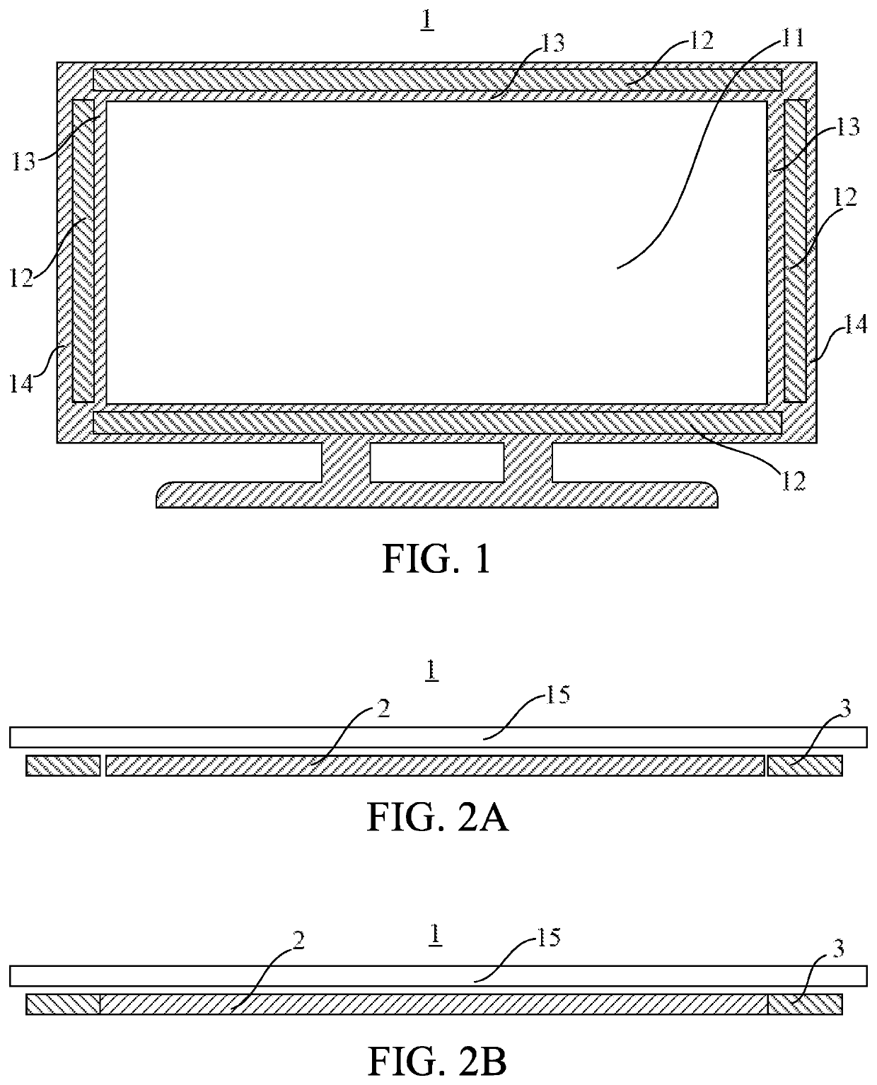
An organic light emitting diode (OLED) display machine with an illumination function is provided. The OLED display machine includes a display region, at least one illumination region, and a drive circuit. An organic light-emitting display device is arranged in the display region. Each illumination region is located at one side edge adjacent to the display region. An organic light-emitting illumination device is disposed in the illumination region. The organic light-emitting illumination device includes a substrate, an insulating layer, a planarization layer, an anode electrode, a light-emitting material layer, and a cathode electrode. The drive circuit is electrically connected to the anode electrode and the cathode electrode of the organic light-emitting illumination device to control an ON or OFF state of the organic light-emitting illumination device. Accordingly, the present invention provides not only a display function, but also illumination, so facilitate wide application and development of the OLED display machine.

Description

1. FIELD OF DISCLOSURE[0001]The present invention relates to a field of display devices and in particular, to an organic light emitting diode (OLED) display machine with an illumination function.2. DESCRIPTION OF RELATED ART[0002]Compared with liquid crystal display (LCD) devices, organic light emitting diode (OLED) displays have advantages such as self-luminescence, fast responses, wide viewing angles, high brightness, colorful colors, and being light in weight. Since OLED displays are thinner and lighter than LCD displays using separate light sources, it is relatively easy for the OLED displays to provide flexible and foldable display features. However, as display devices are used more and more extensively, existing OLED displays are used in terminals, such as a television, a notebook, and a tablet computer. The existing OLED displays have display functions but have no illumination functions, so they fail to provide plenty of functions, lack versatility, and cannot meet the needs ...

Claims


Application Information

Patent Timeline
Patent Type & Authority Patents(United States)
IPC IPC(8): H01L27/32H01L51/52G09G3/3225
CPCG09G3/3225H01L27/322H01L27/3272H01L51/5237G09G2320/0233G09G2330/027H01L2251/533H01L2251/5361H10K59/87H10K59/00H10K59/38H10K59/122H10K50/84H10K59/126H10K2102/3035
Inventor TANG, YUEJUNLI, XUEYUN
Owner WUHAN CHINA STAR OPTOELECTRONICS TECH CO LTD
Learn More