
Gate drive apparatus and control method

a gate drive and control method technology, applied in the direction of power conversion systems, pulse techniques, diodes, etc., can solve problems such as design contradictions, achieve the effects of simple and reliable, improve the efficiency and switching performance of inverters, and improve the rise time of gate drive signals

Active Publication Date: 2021-08-24
DIODES INC
View PDF2 Cites 0 Cited by
  • Summary
  • Abstract
  • Description
  • Claims
  • Application Information

AI Technical Summary

Benefits of technology

The present invention relates to a gate drive circuit for improving the efficiency and switching performance of an inverter. The circuit includes a depletion mode device that helps to reduce the leakage current of the gate drive circuit. The resistance value of the resistor is selected based on the principle of improving the rise time of the gate drive signal when a logic low signal is applied to the high-side switch. The circuit can be implemented in different ways, such as using a controllable switch and a resistor in series or parallel with the switch, or using a combination of two resistors. The technical effect of the invention is to improve the efficiency and switching performance of the inverter by reducing leakage current and improving the rise time of the gate drive signal.

Problems solved by technology

The design incompatibility between a fast rise time and a reduced leakage current may result in a design contradiction.

Method used


Image

  • Gate drive apparatus and control method
  • Gate drive apparatus and control method
  • Gate drive apparatus and control method

Examples


Embodiment Construction

[0024]The present invention will be described with respect to preferred embodiments in a specific context, namely a gate drive circuit for driving an inverter. The invention may also be applied, however, to a variety of power conversion systems. Hereinafter, various embodiments will be explained in detail with reference to the accompanying drawings.

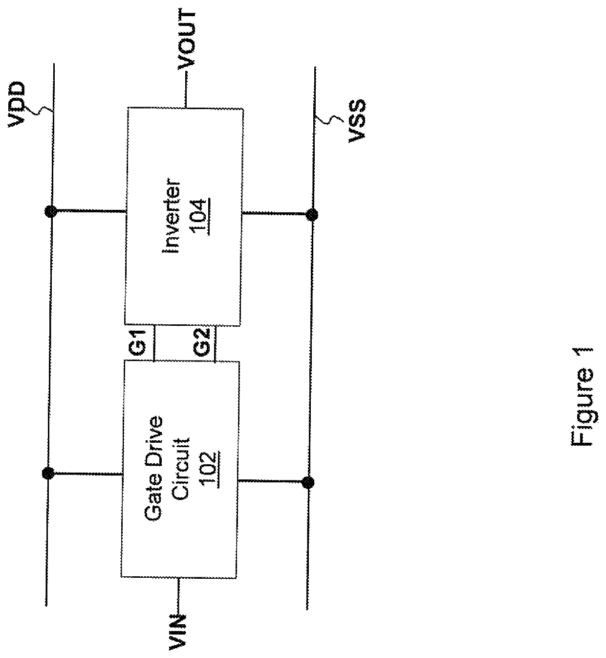
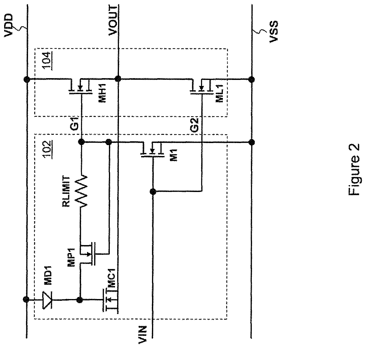
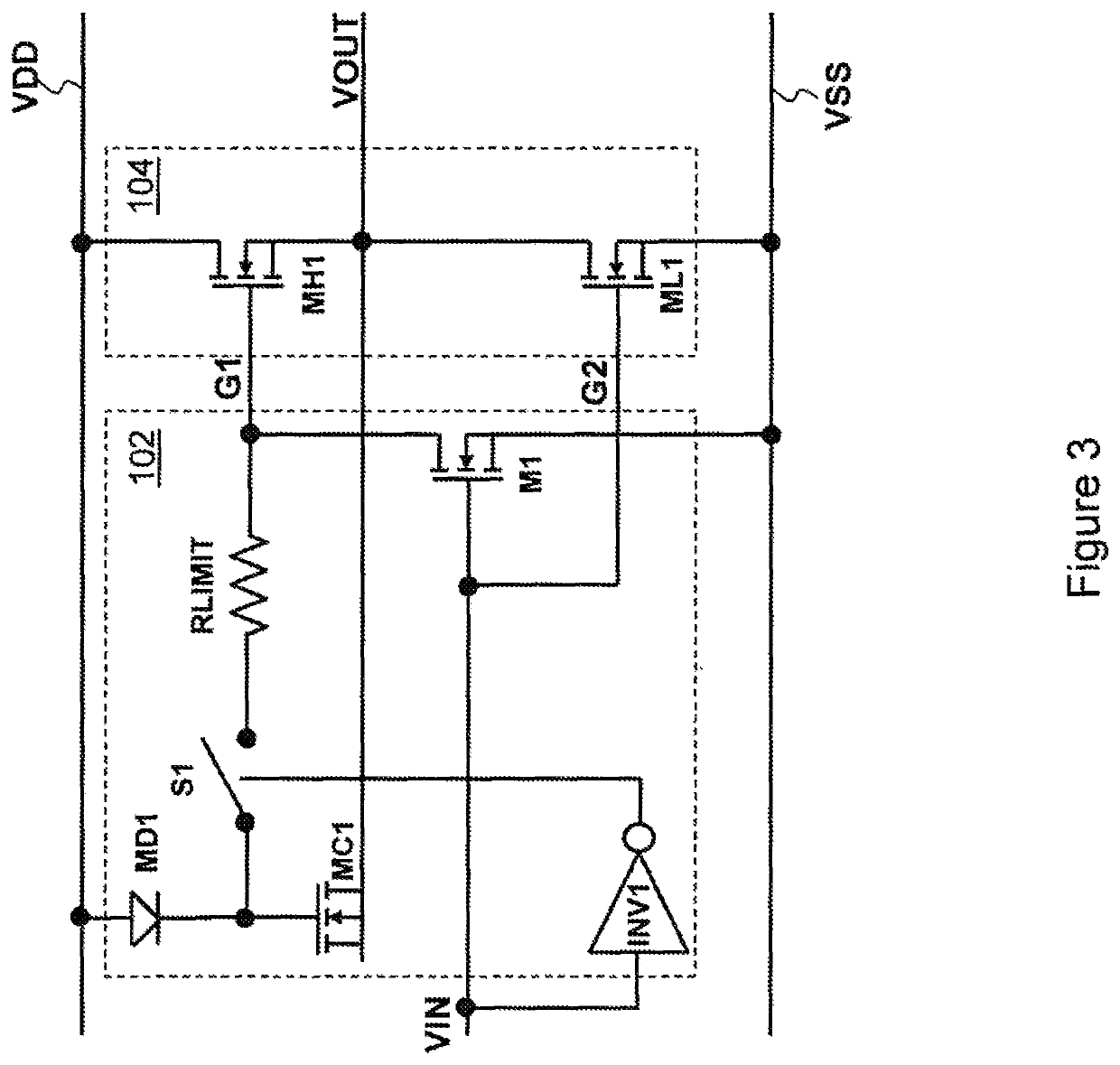
[0025]FIG. 1 depicts a block diagram of an inverter and its associated gate drive circuit. An inverter 104 is connected between a first voltage bus VDD and a second voltage bus VSS. The inverter 104 is configured to receive two gate drive signals, namely a first gate drive signal G and a second gate drive signal G2. A gate drive circuit 102 is connected between the first voltage bus VDD and the second voltage bus VSS. The gate drive circuit 102 is configured to receive an input signal VIN. The gate drive circuit 102 converts the input signal VIN into the gate drive signals G1 and G2. FIG. 1 depicts the gate drive circuit 102 and the inver...


PUM


Abstract

An apparatus includes a capacitive device configured to provide bias power for a high-side switch, a gate drive path having variable resistance connected between the capacitive device and a gate of the high-side switch, wherein the gate drive path having variable resistance is of a first resistance value in response to a turn-on of the high-side switch, and the gate drive path having variable resistance is of a second resistance value in response to a turn-off of the high-side switch, and wherein the second resistance value is greater than the first resistance value, and a control switch connected between the gate of the high-side switch and ground.

Description

TECHNICAL FIELD[0001]The present invention relates to a gate drive apparatus, and, in particular embodiments, to a gate drive apparatus for an inverter.BACKGROUND[0002]An inverter includes two switches connected in series between a power source and ground. The switch connected to the power source is commonly known as a high-side switch, and the switch connected to ground is commonly known as a low-side switch. A high-side drive circuit and a low-side drive circuit are employed to control the gates of the high-side switch and the low-side switch respectively. In order to turn on the high-side switch, the high-side drive circuit may need a gate voltage higher than the voltage of the power source. This may be accomplished with a bootstrap capacitor circuit.[0003]Kinzer (U.S. Patent Application 2017 / 0222644) discloses a GaN gate drive circuit including a bootstrap capacitor configured for driving the high-side switch of the inverter. The bootstrap capacitor is connected to the gate of t...

Claims


Application Information

Patent Timeline
Patent Type & Authority Patents(United States)
IPC IPC(8): H03K17/693H03K17/687
CPCH03K17/693H03K2017/6875H03K2217/0063H03K2217/0081H03K17/063H03K2217/0072H02M7/537H02M1/08H01L27/0629
Inventor CHUANG, CHIAO-SHUNKUO, TACHUANCHEN, KE-HORNG
Owner DIODES INC
Learn More